DOCA GPUNetIO
本文档概述了 DOCA GPUNetIO API 及其配置说明。
网络数据包的实时 GPU 处理是一种对以下应用领域有用的技术:信号处理、网络安全、信息收集、输入重建等等。这些应用涉及 CPU 在关键路径(以 CPU 为中心的方法)中协调网卡 (NIC),以在 GPU 内存 (GPUDirect RDMA) 中接收数据包,并通知在 GPU 上等待新数据包集的包处理 CUDA 内核。在低功耗平台中,CPU 很容易成为瓶颈,掩盖 GPU 的价值。目标是在尽可能低的延迟下最大化零丢包吞吐量。
当连接到应用程序的客户端数量增加时,以 CPU 为中心的方法可能不具有可扩展性,因为同一队列(客户端)上两次接收操作之间的时间会随着队列数量的增加而增加。新的 DOCA GPUNetIO 库允许开发人员在优化性能的同时编排这些类型的应用程序,结合 GPUDirect RDMA 以实现数据路径加速,GDRCopy 库使 CPU 可以直接访问 GPU 内存,以及 GPUDirect 异步内核启动网络 (GDAKIN) 通信,以允许 CUDA 内核直接控制 NIC。
以 CPU 为中心的方法
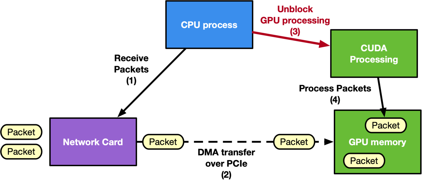
以 GPU 为中心的方法
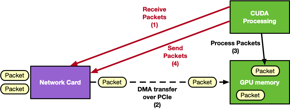
DOCA GPUNetIO 支持以 GPU 为中心的解决方案,通过提供以下功能将 CPU 从关键路径中移除
GPUDirect 异步内核启动技术 – GPU CUDA 内核可以直接控制其他硬件组件,如网卡或 NVIDIA® BlueField® 的 DMA 引擎
GDAKIN 通信 – GPU CUDA 内核可以控制网络通信以发送或接收数据
GPU 可以控制以太网通信
GPU 可以控制 RDMA 通信(支持 InfiniBand 或 RoCE)
应用程序关键路径中不需要 CPU 干预
DMA 引擎 – GPU CUDA 内核可以使用 BlueField 的 DMA 引擎触发内存复制
GPUDirect RDMA – 使用连续的 GPU 内存来发送或接收 RDMA 数据或以太网数据包,而无需 CPU 内存暂存副本
信号量 – 在两个 CUDA 内核或一个 CUDA 内核和一个 CPU 线程之间提供标准化的低延迟消息传递协议
智能内存分配 – 分配对齐的 GPU 内存缓冲区,可能将其暴露给直接 CPU 访问
CUDA、DPDK gpudev 库和 GDRCopy 库的组合,这些库已嵌入到随 DOCA 发布的 DPDK 中
精确的发送调度 – 根据用户提供的时间戳安排未来以太网数据包的发送
Aerial 5G SDK、Morpheus 和 Holoscan 高级网络运算符 是 NVIDIA 应用程序积极使用 DOCA GPUNetIO 的示例。
要深入了解这项技术和动机,请参阅 NVIDIA 博客文章 使用 NVIDIA DOCA GPUNetIO 进行内联 GPU 数据包处理 和 使用 NVIDIA DOCA GPUNetIO 解锁 GPU 加速 RDMA。另一篇 NVIDIA 博客文章 利用 NVIDIA DOCA GPUNetIO 实现实时网络处理的强大功能 已发布,以提供更多用例示例,说明 DOCA GPUNetIO 如何有效地改进执行。
DOCA GPUNetIO 上的 RDMA 目前在 Alpha 级别受支持。
2.10 版本变更
以下部分详细介绍了 2.10 版本中的 doca_gpunetio 库更新。
移除了对 DPDK 的依赖 – 到目前为止,在调用
doca_gpu_create之前需要rte_eal_init函数。在以太网或 RDMA 应用程序/示例中不再需要这样做。
DOCA GPUNetIO 需要正确配置的环境,这取决于应用程序应在 x86 主机还是 DPU Arm 内核上运行。以下小节描述了两种场景中所需的配置,假设 DOCA、CUDA 工具包和 NVIDIA 驱动程序已安装在构建和执行 DOCA GPUNetIO 的系统(x86 主机或 BlueField Arm)上。
DOCA GPUNetIO 适用于所有可从 此处 下载的用于主机和 BFB 软件包的 DOCA。
假设 DOCA 软件包已下载并且已满足下面列出的先决条件,要安装 DOCA GPUNetIO 组件,请运行
对于 Ubuntu/Debian
apt install doca-all doca-sdk-gpunetio libdoca-sdk-gpunetio-dev
对于 RHEL
yum install doca-all doca-sdk-gpunetio doca-sdk-gpunetio-devel
系统的内部硬件拓扑结构应该是 GPUDirect-RDMA 友好的,以便 最大化 GPU 和 NIC 之间的内部吞吐量。
为了获得最佳性能,在构建任何 DOCA GPUNetIO 示例或应用程序时,请在 meson.build 文件中将 buildtype 设置为 release 而不是 debug。
由于 DOCA GPUNetIO 同时存在于 DOCA-for-Host 和 DOCA BFB(用于 BlueField Arm)中,因此 GPUNetIO 应用程序可以在主机 CPU 或 BlueField 的 Arm 内核上执行。以下小节提供了两种场景的描述。
DOCA GPUNetIO 已在裸机和 Docker 中进行过测试,但从未在虚拟化环境中进行过测试。目前不建议使用 KVM。
主机 CPU 上的应用程序
假设 DOCA GPUNetIO 应用程序在主机 x86 CPU 内核上运行,强烈建议 GPU 和 NIC 之间具有专用的 PCIe 连接。这种拓扑结构可以通过两种方式实现
向其中一个 PCIe 根复合体插槽添加一个额外的 PCIe 交换机,并将 GPU 和 NVIDIA® ConnectX® 适配器连接到该交换机
将 NVIDIA® 融合加速器 DPU 连接到 PCIe 根复合体,并将其设置为 NIC 模式(即,将 GPU 和 NIC 设备暴露给主机)
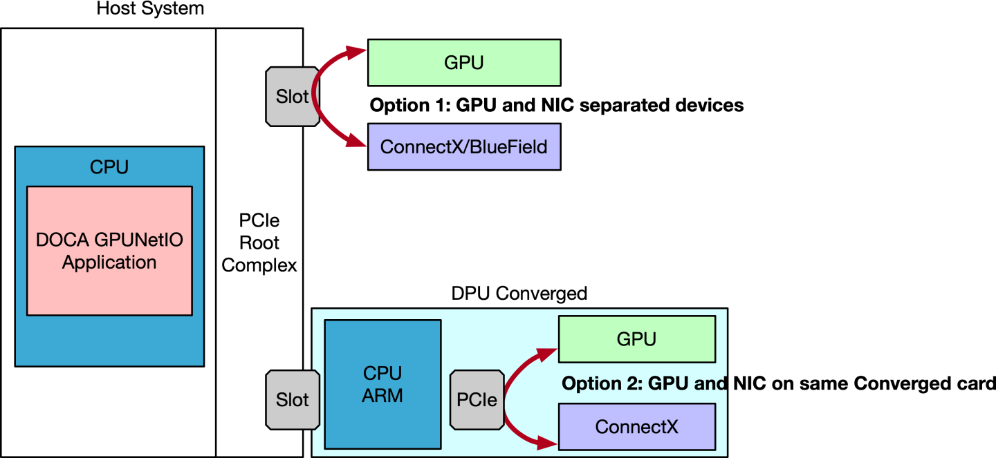
您可以使用 lspci -tvvv 或 nvidia-smi topo -m 检查系统的拓扑结构。
选项 1:以太网模式下的 ConnectX 适配器
NVIDIA® ConnectX® 固件必须为 22.36.1010 或更高版本。强烈建议仅使用 ConnectX-6 Dx 及更高版本的 NVIDIA 适配器。
DOCA GPUNetIO 允许 CUDA 内核在使用以太网协议时控制 NIC。因此,ConnectX 必须设置为以太网模式。
为此,请按照以下步骤操作
启动 MST,检查状态,并复制 MST 设备名称
# Start MSTmst start mst status -vMST modules: ------------ MST PCI module is not loaded MST PCI configuration module loaded PCI devices: ------------ DEVICE_TYPE MST PCI RDMA NET NUMA ConnectX6DX(rev:0) /dev/mst/mt4125_pciconf0.1 b5:00.1 mlx5_1 net-ens6f1 0 ConnectX6DX(rev:0) /dev/mst/mt4125_pciconf0 b5:00.0 mlx5_0 net-ens6f0 0将 NIC 配置为以太网模式,并启用精确发送调度(如果在发送端需要)
信息以下示例假设适配器是双端口的。如果是单端口,则仅应用 P1 选项。
mlxconfig -d <mst_device> s KEEP_ETH_LINK_UP_P1=1 KEEP_ETH_LINK_UP_P2=1 KEEP_IB_LINK_UP_P1=0 KEEP_IB_LINK_UP_P2=0 mlxconfig -d <mst_device> --
yessetACCURATE_TX_SCHEDULER=1 REAL_TIME_CLOCK_ENABLE=1执行冷重启以应用配置更改
ipmitool power cycle
选项 2:NIC 模式下的 DPU 融合加速器
要将融合加速器 DPU 上的 GPU 和 NIC 暴露给在主机 x86 上运行的应用程序并使用它们,请将 DPU 配置为在 NIC 模式下运行。
为此,请按照以下步骤操作
适用于 NVIDIA® BlueField®-2 和 NVIDIA® BlueField®-3 融合加速器 DPU。
启动 MST,检查状态,并复制 MST 设备名称
# Enable MSTsudomst startsudomst status MST devices: ------------ /dev/mst/mt41686_pciconf0 - PCI configuration cycles access. domain:bus:dev.fn=0000:b8:00.0 addr.reg=88 data.reg=92 cr_bar.gw_offset=-1 Chip revision is: 01将融合加速器 DPU 上的 GPU 暴露给主机。
对于 BlueField-2,
PCI_DOWNSTREAM_PORT_OWNER偏移量必须设置为 4sudomlxconfig -d <mst_device> --yess PCI_DOWNSTREAM_PORT_OWNER[4]=0x0对于 BlueField-3,
PCI_DOWNSTREAM_PORT_OWNER偏移量必须设置为 8sudomlxconfig -d <mst_device> --yess PCI_DOWNSTREAM_PORT_OWNER[8]=0x0
将 BlueField 设置为以太网模式,启用精确发送调度(如果在发送端需要),并将其设置为 NIC 模式
sudomlxconfig -d <mst_device> --yessetLINK_TYPE_P1=2 LINK_TYPE_P2=2 INTERNAL_CPU_MODEL=1 INTERNAL_CPU_PAGE_SUPPLIER=1 INTERNAL_CPU_ESWITCH_MANAGER=1 INTERNAL_CPU_IB_VPORT0=1 INTERNAL_CPU_OFFLOAD_ENGINE=DISABLEDsudomlxconfig -d <mst_device> --yessetACCURATE_TX_SCHEDULER=1 REAL_TIME_CLOCK_ENABLE=1执行冷重启以应用配置更改
ipmitool power cycle
验证配置
sudomlxconfig -d <mst_device> q LINK_TYPE_P1 LINK_TYPE_P2 INTERNAL_CPU_MODEL INTERNAL_CPU_PAGE_SUPPLIER INTERNAL_CPU_ESWITCH_MANAGER INTERNAL_CPU_IB_VPORT0 INTERNAL_CPU_OFFLOAD_ENGINE ACCURATE_TX_SCHEDULER REAL_TIME_CLOCK_ENABLE LINK_TYPE_P1 ETH(2) LINK_TYPE_P2 ETH(2) INTERNAL_CPU_MODEL EMBEDDED_CPU(1) INTERNAL_CPU_PAGE_SUPPLIER EXT_HOST_PF(1) INTERNAL_CPU_ESWITCH_MANAGER EXT_HOST_PF(1) INTERNAL_CPU_IB_VPORT0 EXT_HOST_PF(1) INTERNAL_CPU_OFFLOAD_ENGINE DISABLED(1) ACCURATE_TX_SCHEDULER True(1) REAL_TIME_CLOCK_ENABLE True(1)
BlueField 融合 Arm CPU 上的应用程序
在这种情况下,DOCA GPUNetIO 在 BlueField 的 CPU Arm 内核上运行,使用同一 BlueField 上的 GPU 和 NIC。
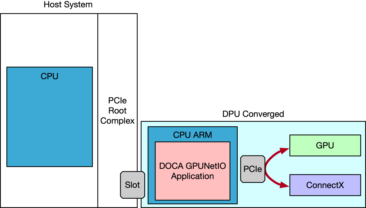
融合加速器 DPU 必须在刷入正确的 BFB 映像后设置为 CPU 模式(有关详细信息,请参阅 DOCA Linux 安装指南)。从 x86 主机,按照以下步骤配置 DPU
适用于 BlueField-2 和 BlueField-3 融合加速器 DPU。
启动 MST,检查状态,并复制 MST 设备名称
# Enable MSTsudomst startsudomst status MST devices: ------------ /dev/mst/mt41686_pciconf0 - PCI configuration cycles access. domain:bus:dev.fn=0000:b8:00.0 addr.reg=88 data.reg=92 cr_bar.gw_offset=-1 Chip revision is: 01将 DPU 设置为 GPU 所有者。
对于 BlueField-2,
PCI_DOWNSTREAM_PORT_OWNER偏移量必须设置为 4sudomlxconfig -d <mst_device> --yess PCI_DOWNSTREAM_PORT_OWNER[4]=0xF对于 BlueField-3,
PCI_DOWNSTREAM_PORT_OWNER偏移量必须设置为 8sudomlxconfig -d <mst_device> --yess PCI_DOWNSTREAM_PORT_OWNER[8]=0xF
将 BlueField 设置为以太网模式,并启用精确发送调度(如果在发送端需要)
sudomlxconfig -d <mst_device> --yessetLINK_TYPE_P1=2 LINK_TYPE_P2=2 INTERNAL_CPU_MODEL=1 INTERNAL_CPU_PAGE_SUPPLIER=0 INTERNAL_CPU_ESWITCH_MANAGER=0 INTERNAL_CPU_IB_VPORT0=0 INTERNAL_CPU_OFFLOAD_ENGINE=ENABLEDsudomlxconfig -d <mst_device> --yessetACCURATE_TX_SCHEDULER=1 REAL_TIME_CLOCK_ENABLE=1执行冷重启以应用配置更改
ipmitool power cycle
验证配置
            mlxconfig -d <mst_device> q LINK_TYPE_P1 LINK_TYPE_P2 INTERNAL_CPU_MODEL INTERNAL_CPU_PAGE_SUPPLIER INTERNAL_CPU_ESWITCH_MANAGER INTERNAL_CPU_IB_VPORT0 INTERNAL_CPU_OFFLOAD_ENGINE ACCURATE_TX_SCHEDULER REAL_TIME_CLOCK_ENABLE
...
Configurations:                                         Next Boot
        LINK_TYPE_P1                                    ETH(2)
        LINK_TYPE_P2                                    ETH(2)
        INTERNAL_CPU_MODEL                              EMBEDDED_CPU(1)
        INTERNAL_CPU_PAGE_SUPPLIER                      ECPF(0)
        INTERNAL_CPU_ESWITCH_MANAGER                    ECPF(0)
        INTERNAL_CPU_IB_VPORT0                          ECPF(0)
        INTERNAL_CPU_OFFLOAD_ENGINE                     ENABLED(0)
        ACCURATE_TX_SCHEDULER                           True(1)
        REAL_TIME_CLOCK_ENABLE                          True(1)
此时,应该可以 SSH 进入 BlueField 以访问其上安装的操作系统。在如前所述安装 DOCA GPUNetIO 之前,必须安装 CUDA 工具包(和 NVIDIA 驱动程序)。
PCIe 配置
在某些 x86 系统上,必须禁用访问控制服务 (ACS),以确保 NIC 和 GPU 之间的直接通信,无论它们是位于同一融合加速器 DPU 上还是位于系统中的不同 PCIe 插槽上。建议的解决方案是通过 BIOS 禁用 ACS 控制(例如,Supermicro 或 HPE) 在 PCIe 桥上。或者,也可以通过命令行禁用它,但这可能不如 BIOS 选项有效。假设系统拓扑结构 选项 2,使用融合加速器 DPU,如下所示
            $ lspci -tvvv...+-[0000:b0]-+-00.0  Intel Corporation Device 09a2
 |           +-00.1  Intel Corporation Device 09a4
 |           +-00.2  Intel Corporation Device 09a3
 |           +-00.4  Intel Corporation Device 0998
 |           \-02.0-[b1-b6]----00.0-[b2-b6]--+-00.0-[b3]--+-00.0  Mellanox Technologies MT42822 BlueField-2 integrated ConnectX-6 Dx network controller
 |                                           |            +-00.1  Mellanox Technologies MT42822 BlueField-2 integrated ConnectX-6 Dx network controller
 |                                           |            \-00.2  Mellanox Technologies MT42822 BlueField-2 SoC Management Interface
 |                                           \-01.0-[b4-b6]----00.0-[b5-b6]----08.0-[b6]----00.0  NVIDIA Corporation Device 20b8
要考虑的 PCIe 交换机地址是 b2:00.0(DPU 的入口点)。ACSCtl 必须具有所有负值
PCIe 设置
setpci -s b2:00.0 ECAP_ACS+0x6.w=0000
要验证设置是否已正确应用
PCIe 检查
            $ sudo lspci -s b2:00.0 -vvvv | grep -i ACSCtl
ACSCtl: SrcValid- TransBlk- ReqRedir- CmpltRedir- UpstreamFwd- EgressCtrl- DirectTrans-
如果应用程序仍然没有报告收到任何数据包,请尝试禁用 IOMMU。在某些系统上,可以通过 BIOS 查找 NorthBridge 配置中的 VT-d 或 IOMMU 并将该设置更改为 Disable 并保存来实现。系统可能还需要将 intel_iommu=off 或 amd_iommu=off 添加到内核选项。这可以通过 grub 命令行完成,如下所示
IOMMU
            $ sudo vim /etc/default/grub
# GRUB_CMDLINE_LINUX_DEFAULT="iommu=off intel_iommu=off <more options>"
$ sudo update-grub
$ sudo reboot
GPU 配置
CUDA 工具包 12.1 或更高版本必须安装在主机上。还建议启用持久模式以减少初始应用程序延迟 nvidia-smi -pm 1。
GDRCopy
为了允许 CPU 直接访问 GPU 内存而无需 CUDA API,DPDK 和 DOCA 需要在系统上安装 GDRCopy 内核模块
GDRCopy 配置
            # Install GDRCopy
sudo apt install -y check kmod
git clone https://github.com/NVIDIA/gdrcopy.git /opt/mellanox/gdrcopy
cd /opt/mellanox/gdrcopy
make
# Run gdrdrv kernel module
./insmod.sh

# Double check nvidia-peermem and gdrdrv module are running
$ lsmod | egrep gdrdrv
gdrdrv                 24576  0
nvidia              55726080  4 nvidia_uvm,nvidia_peermem,gdrdrv,nvidia_modeset

# Export library path
export LD_LIBRARY_PATH=${LD_LIBRARY_PATH}:/opt/mellanox/gdrcopy/src

# Ensure CUDA library path is in the env var
export PATH="/usr/local/cuda/bin:${PATH}"
export LD_LIBRARY_PATH="/usr/local/cuda/lib:/usr/local/cuda/lib64:${LD_LIBRARY_PATH}"
export CPATH="$(echo /usr/local/cuda/targets/{x86_64,sbsa}-linux/include | sed 's/ /:/'):${CPATH}"
GPU 内存映射 (nvidia-peermem vs. dmabuf)
为了允许 NIC 使用 GPU 内存发送和接收数据包,需要启动 NVIDIA 内核模块 nvidia-peermem。它默认随 CUDA 工具包安装一起提供。
启动 nvidia-peermem
sudo modprobe nvidia-peermem
通过 nvidia-peermem 模块映射缓冲区是旧版映射模式。
或者,DOCA 提供了通过 dmabuf 映射 GPU 内存的能力,提供了一组高级函数。先决条件是在具有以下条件的系统上安装 DOCA
Linux 内核 ≥ 6.2
libibverbs ≥ 1.14.44
CUDA 工具包 12.5 或更旧版本 – 使用
-m=kernel-open标志安装(这意味着开源模式下的 NVIDIA 驱动程序)CUDA 工具包 12.6 或更新版本 – 默认启用开放内核模式
在内核 6.2 上安装 DOCA 以启用 dmabuf 是一项实验性功能。
可以在 DOCA GPU 数据包处理应用程序中找到一个示例
GPU 配置
            /* Get from CUDA the dmabuf file-descriptor for the GPU memory buffer */
result = doca_gpu_dmabuf_fd(gpu_dev, gpu_buffer_addr, gpu_buffer_size, &(dmabuf_fd));
if (result != DOCA_SUCCESS) {
	/* If it fails, create a DOCA mmap for the GPU memory buffer with the nvidia-peermem legacy method */
	doca_mmap_set_memrange(gpu_buffer_mmap, gpu_buffer_addr, gpu_buffer_size);
} else {
	/* If it succeeds, create a DOCA mmap for the GPU memory buffer using the dmabuf method */
	doca_mmap_set_dmabuf_memrange(gpu_buffer_mmap, dmabuf_fd, gpu_buffer_addr, 0, gpu_buffer_size);
}
如果函数 doca_gpu_dmabuf_fd 失败,则可能意味着 NVIDIA 驱动程序未以开源模式安装。
稍后,在调用 doca_mmap_start 时,DOCA 库会尝试使用 dmabuf 文件描述符映射 GPU 内存缓冲区。如果失败(Linux 系统上设置错误),它会回退尝试使用旧版模式 (nvidia-peermem) 映射 GPU 缓冲区。如果失败,则会返回信息性错误。
GPU BAR1 大小
每次将 GPU 缓冲区映射到 NIC 时(例如,与发送或接收队列关联的缓冲区),都会使用一部分 GPU BAR1 映射空间。因此,检查 BAR1 映射是否足够大以容纳 DOCA GPUNetIO 应用程序尝试映射的所有字节非常重要。要验证 GPU 的 BAR1 映射空间,您可以使用 nvidia-smi
BAR1 映射
            $ nvidia-smi -q

==============NVSMI LOG==============
.....
Attached GPUs                             : 1
GPU 00000000:CA:00.0
    Product Name                          : NVIDIA A100 80GB PCIe
    Product Architecture                  : Ampere
    Persistence Mode                      : Enabled
.....
    BAR1 Memory Usage
        Total                             : 131072 MiB
        Used                              : 1 MiB
        Free                              : 131071 MiB
默认情况下,某些 GPU(例如 RTX 型号)可能具有非常小的 BAR1 大小
BAR1 映射
            $ nvidia-smi -q | grep -i bar -A 3
	BAR1 Memory Usage
	Total : 256 MiB
	Used : 6 MiB
	Free : 250 MiB
如果 BAR1 大小不足,DOCA GPUNetIO 应用程序可能会因错误而退出,因为 DOCA mmap 无法将 GPU 内存缓冲区映射到 NIC(例如,Failed to start mmap DOCA Driver call failure)。要克服此问题,必须从 BIOS 增加 GPU BAR1。系统应启用“Resizable BAR”选项。有关更多信息,请参阅 此 NVIDIA 论坛帖子。
BlueField-3 特定配置
要在融合卡中(“BlueField 融合 Arm CPU 上的应用程序”部分)在 BlueField-3 Arm 内核上运行 DOCA GPUNetIO 应用程序,必须在驱动程序配置文件末尾设置 NVIDIA 驱动程序选项
设置 NVIDIA 驱动程序选项
            cat <<EOF | sudo tee /etc/modprobe.d/nvidia.conf
options nvidia NVreg_RegistryDwords="RmDmaAdjustPeerMmioBF3=1;"
EOF
要确保 NVIDIA 驱动程序已检测到该选项,请运行
检查 NVIDIA 驱动程序选项
            $ grep RegistryDwords /proc/driver/nvidia/params
RegistryDwords: "RmDmaAdjustPeerMmioBF3=1;"
RegistryDwordsPerDevice: ""
GPU 数据包处理网络应用程序可以分为两个基本阶段
CPU 上的设置(设备配置、内存分配、启动 CUDA 内核等)
主数据路径,GPU 和 NIC 在其中交互以执行其功能
DOCA GPUNetIO 提供不同的构建块,其中一些与 DOCA 以太网 或 DOCA RDMA 库结合使用,以创建完全在 GPU 上运行的完整管道。
在 CPU 上的设置阶段,应用程序必须
准备 CPU 上的所有对象。
为它们导出 GPU 句柄。
传递对象 GPU 句柄以在数据路径期间使用该对象,从而启动 CUDA 内核。
因此,DOCA GPUNetIO 由两个库组成
libdoca_gpunetio具有由 CPU 调用的函数,用于准备 GPU、分配内存和对象libdoca_gpunetio_device具有由 GPU 在 CUDA 内核中的数据路径期间调用的函数
DOCA GPUNetIO 共享库的 pkgconfig 文件是 doca-gpunetio.pc。但是,DOCA GPUNetIO CUDA 设备静态库 /opt/mellanox/doca/lib/x86_64-linux-gnu/libdoca_gpunetio_device.a 没有 pkgconfig 文件,因此如果需要 DOCA GPUNetIO CUDA 设备函数,则必须将其显式链接到 CUDA 应用程序。
下图展示了典型流程
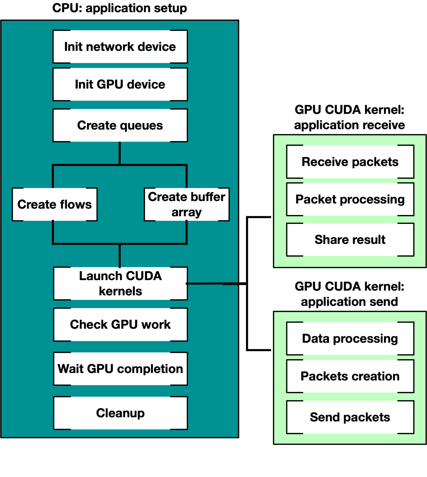
有关使用 DOCA GPUNetIO 发送和接收以太网数据包的示例,请参阅 DOCA GPU 数据包处理应用程序指南。
本节详细介绍了与 CPU 和 GPU 上主要 DOCA GPUNetIO API 相关的特定结构和操作。GPUNetIO 标头包括
doca_gpunetio.h– CPU 函数doca_gpunetio_dev_buf.cuh– 用于管理 DOCA 缓冲区数组的 GPU 函数doca_gpunetio_dev_eth_rxq.cuh– 用于管理 DOCA 以太网接收队列的 GPU 函数doca_gpunetio_dev_eth_txq.cuh– 用于管理 DOCA 以太网发送队列的 GPU 函数doca_gpunetio_dev_sem.cuh– 用于管理 DOCA GPUNetIO 信号量的 GPU 函数doca_gpunetio_dev_rdma.cuh– 用于管理 DOCA RDMA 队列的 GPU 函数doca_gpunetio_dev_dma.cuh– 用于管理 DOCA DMA 队列的 GPU 函数
本节列出了 DOCA GPUNetIO 的主要函数。为了更好地理解它们的用法,请参阅“构建块”部分,其中包含多个代码示例。
为了更好地理解与以太网发送和接收相关的结构、对象和函数,请参阅 DOCA 以太网。
为了更好地理解与 RDMA 操作相关的结构、对象和函数,请参阅 DOCA RDMA。
为了更好地理解与 DMA 操作相关的结构、对象和函数,请参阅 DOCA DMA。
为了更好地理解 DOCA 核心对象(如 doca_mmap 或 doca_buf_array),请参阅 DOCA Core。
所有与 GPUNetIO 一起使用的 DOCA Core 和以太网对象都具有 GPU 导出函数,用于获取该对象的 GPU 句柄。以下是一些示例
doca_buf_array导出为doca_gpu_buf_arrDOCA 缓冲区数组
structdoca_mmap *mmap;structdoca_buf_arr *buf_arr_cpu;structdoca_gpu_buf_arr *buf_arr_gpu; doca_mmap_create(&(mmap));/* Populate and start mmap */doca_buf_arr_create(mmap, &buf_arr_cpu);/* Populate and start buf arr attributes. Set datapath on GPU *//* Export the buf array CPU handler to a buf array GPU handler */doca_buf_arr_get_gpu_handle(buf_arr_cpu, &(buf_arr_gpu));/* To use the GPU handler, pass it as parameter of the CUDA kernel */cuda_kernel<<<...>>>(buf_arr_gpu, ...);doca_eth_rxq导出为doca_gpu_eth_rxqDOCA 缓冲区数组
structdoca_mmap *mmap;structdoca_eth_rxq *eth_rxq_cpu;structdoca_gpu_eth_rxq *eth_rxq_gpu;structdoca_dev *ddev;/* Create DOCA network device ddev *//* Create the DOCA Ethernet receive queue */doca_eth_rxq_create(ddev, MAX_NUM_PACKETS, MAX_PACKET_SIZE, ð_rxq_cpu,);/* Populate and start Ethernet receive queue attributes. Set datapath on GPU *//* Export the Ethernet receive queue CPU handler to a Ethernet receive queue GPU handler */doca_eth_rxq_get_gpu_handle(eth_rxq_cpu, &(eth_rxq_gpu));/* To use the GPU handler, pass it as parameter of the CUDA kernel */cuda_kernel<<<...>>>(eth_rxq_gpu, ...);
CPU 函数
本节列出了只能在 CPU 上使用的 DOCA GPUNetIO 函数。
doca_gpu_mem_type
此枚举列出了可以使用 GPUNetIO 分配的所有可能的内存类型。
            enum doca_gpu_mem_type {
    DOCA_GPU_MEM_TYPE_GPU        = 0,
    DOCA_GPU_MEM_TYPE_GPU_CPU    = 1,
    DOCA_GPU_MEM_TYPE_CPU_GPU    = 2,
};
关于语法,DOCA_GPU_MEM_TYPE_ 前缀后的文本字符串表示 <内存驻留位置>_<谁有权访问>。
DOCA_GPU_MEM_TYPE_GPU– 内存驻留在 GPU 上,并且只能从 GPU 访问DOCA_GPU_MEM_TYPE_GPU_CPU– 内存驻留在 GPU 上,CPU 也可以访问DOCA_GPU_MEM_TYPE_CPU_GPU– 内存驻留在 CPU 上,GPU 也可以访问
DOCA_GPU_MEM_TYPE_GPU_CPU 内存类型的典型用法是从 CPU 向 GPU 发送通知(例如,CUDA 内核定期检查以查看是否满足 CPU 设置的退出条件)。
doca_gpu_create
这是 GPUNetIO 应用程序必须调用的第一个函数,用于在 GPU 设备上创建句柄。该函数初始化内存中类型为 struct doca_gpu * 的结构的指针。
doca_error_t doca_gpu_create(const char *gpu_bus_id, struct doca_gpu **gpu_dev);
gpu_bus_id– 要在应用程序中使用的 GPU 设备的<PCIe 总线>:<设备>.<功能>gpu_dev [out]– 该 GPU 设备的 GPUNetIO 句柄
要获取 PCIe 地址,用户可以使用命令 lspci 或 nvidia-smi。
doca_gpu_mem_alloc
此 CPU 函数分配不同类型的内存。
doca_error_t doca_gpu_mem_alloc(struct doca_gpu *gpu_dev, size_t size, size_t alignment, enum doca_gpu_mem_type mtype, void **memptr_gpu, void **memptr_cpu)
gpu_dev– GPUNetIO 设备句柄size– 要分配的内存区域的大小(以字节为单位)alignment– 要使用的内存地址对齐方式。如果为 0,将使用默认对齐方式mtype– 要分配的内存类型memptr_gpu [out]– GPU 指针,用于从 GPU 修改该内存(如果内存分配在 GPU 上或 GPU 可见)memptr_cpu[out]– CPU 指针,用于从 CPU 修改该内存(如果内存分配在 CPU 上或 CPU 可见)。如果内存仅供 GPU 使用,则可以为 NULL
确保在正确的设备上使用正确的指针!如果应用程序尝试使用来自 CPU 的 memptr_gpu 地址访问内存,则会导致段错误。
doca_gpu_semaphore_create
创建 DOCA GPUNetIO 信号量的新实例。信号量由项目列表组成,每个项目默认具有状态标志、数据包数量和 doca_gpu_buf_arr 中 doca_gpu_buf 的索引。
例如,GPUNetIO 信号量可用于以下应用程序:CUDA 内核负责在与以太网接收队列对象 doca_gpu_eth_rxq 关联的 doca_gpu_buf_arr 数组中接收数据包(请参阅“doca_gpu_dev_eth_rxq_receive_*”部分),并将数据包信息分派到第二个处理它们的 CUDA 内核。
使用 GPUNetIO 信号量的另一种方法是在不同实体(如两个 CUDA 内核或一个 CUDA 内核和一个 CPU 线程)之间交换数据。这种情况的原因可能是 CUDA 内核需要将数据包处理的结果提供给 CPU,而 CPU 反过来会编译统计报告。因此,可以将自定义应用程序定义的结构与信号量中的每个项目关联。这样,信号量可以用作消息传递对象。
“接收和处理”部分说明了这两种情况。
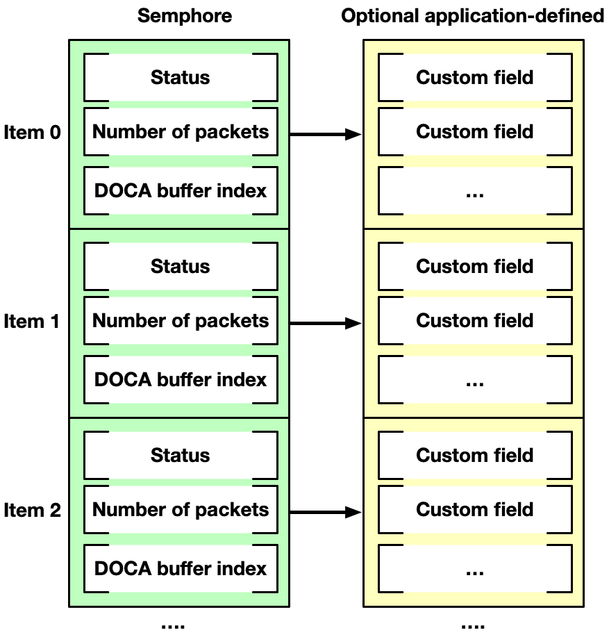
通过信号量通信的实体必须根据以下逻辑采用轮询/更新机制
更新
填充信号量的下一个项目(数据包信息和/或自定义应用程序定义的信息)。
将状态标志设置为 READY。
轮询
等待下一个项目的状态标志等于
READY。读取和处理信息。
将状态标志设置为
DONE。
doca_error_t doca_gpu_semaphore_create(struct doca_gpu *gpu_dev, struct doca_gpu_semaphore **semaphore)
gpu_dev– GPUNetIO 句柄semaphore [out]– 与 GPU 设备关联的 GPUNetIO 信号量句柄
doca_gpu_semaphore_set_memory_type
此函数定义信号量分配的内存类型。
doca_error_t doca_gpu_semaphore_set_memory_type(struct doca_gpu_semaphore *semaphore, enum doca_gpu_mem_type mtype)
semaphore– GPUNetIO 信号量句柄mtype– 用于分配自定义信息结构的内存类型如果应用程序必须仅在 CUDA 内核之间共享数据包信息,则建议使用
DOCA_GPU_MEM_GPU内存类型。如果应用程序必须将信息从 CUDA 内核共享到 CPU(例如,报告管道计算的统计信息或输出),则建议使用
DOCA_GPU_MEM_CPU_GPU内存类型
doca_gpu_semaphore_set_items_num
此函数定义信号量中的项目数。
doca_error_t doca_gpu_semaphore_set_items_num(struct doca_gpu_semaphore *semaphore, uint32_t num_items)
semaphore– GPUNetIO 信号量句柄num_items– 要分配的项目数
doca_gpu_semaphore_set_custom_info
此函数将应用程序特定的结构与信号量项目关联,如“doca_gpu_semaphore_create”下所述。
doca_error_t doca_gpu_semaphore_set_custom_info(struct doca_gpu_semaphore *semaphore, uint32_t nbytes, enum doca_gpu_mem_type mtype)
semaphore– GPUNetIO 信号量句柄nbytes– 要关联的自定义信息结构的大小mtype– 用于分配自定义信息结构的内存类型如果应用程序必须仅在 CUDA 内核之间共享数据包信息,则建议使用
DOCA_GPU_MEM_GPU内存类型如果应用程序必须将信息从 CUDA 内核共享到 CPU(例如,报告管道计算的统计信息或输出),则建议使用
DOCA_GPU_MEM_CPU_GPU内存类型
doca_gpu_semaphore_get_status
从 CPU 查询信号量项目的状态。如果信号量使用 DOCA_GPU_MEM_GPU 分配,则此函数会导致段错误。
doca_error_t doca_gpu_semaphore_get_status(struct doca_gpu_semaphore *semaphore_cpu, uint32_t idx, enum doca_gpu_semaphore_status *status)
semaphore_cpu– GPUNetIO 信号量 CPU 句柄idx– 信号量项目索引status [out]– 输出信号量状态
doca_gpu_semaphore_get_custom_info_addr
从 CPU 检索与信号量项目关联的自定义信息结构的地址。如果信号量或自定义信息使用 DOCA_GPU_MEM_GPU 分配,则此函数会导致段错误。
doca_error_t doca_gpu_semaphore_get_custom_info_addr(struct doca_gpu_semaphore *semaphore_cpu, uint32_t idx, void **custom_info)
semaphore_cpu– GPUNetIO 信号量 CPU 句柄idx– 信号量项目索引custom_info [out]– 输出信号量自定义信息地址
DOCA PE
可以在 CPU 端通过 DOCA PE 跟踪为 GPUNetIO 使用导出的 DOCA 以太网 Txq 上下文,以检查发送数据包时是否存在错误,或在使用 GPU 上的任何 doca_gpu_dev_eth_txq_*_enqueue_* 函数发送数据包后检索通知信息。可以在使用 ICMP 流量的 DOCA GPU 数据包处理应用程序中找到示例。
强模式 vs. 弱模式
某些以太网和 RDMA GPU 函数提供两种操作模式:弱模式和强模式。
在弱模式下,应用程序计算队列中的下一个可用位置。借助
doca_gpu_eth_txq_get_info、doca_gpu_rdma_get_info或doca_gpu_dev_rdma_recv_get_info等函数,可以知道队列中的下一个可用位置以及队列中条目总数的掩码(因此可以包装增量描述符索引)。在这种模式下,开发人员必须为数据包排队的位置指定队列描述符编号,确保队列中没有描述符为空。管理起来有点复杂,但应该可以获得更好的性能,并且开发人员可以强调 GPU 内存合并,使用顺序内存位置对顺序操作进行排队。在强模式下,GPU 函数将以太网/RDMA 操作排队到队列中的下一个可用位置。它更易于管理,因为开发人员不必担心操作的位置,但它可能会引入额外的延迟,以原子方式保证多个线程对同一队列的访问。此外,它不保证顺序操作引用顺序内存位置。
注意所有强模式函数都在 CUDA 块级别工作。也就是说,不可能从两个不同的 CUDA 块同时访问同一个 Eth/RDMA 队列。
在“生成和发送”和“用于 RDMA 写入的 CUDA 内核”部分中,有一些关于如何使用弱模式 API 的示例。
GPU 函数 – 以太网
本节提供可以在 CUDA 内核中仅在 GPU 上用于以太网网络操作的 DOCA GPUNetIO 函数列表。
doca_gpu_dev_eth_rxq_receive_*
为了在 CUDA 内核中获取数据包,DOCA GPUNetIO 针对不同的范围提供了不同类型的接收函数:每个 CUDA 块、每个 CUDA Warp 和每个 CUDA 线程。
            __device__ doca_error_t doca_gpu_dev_eth_rxq_receive_block(struct doca_gpu_eth_rxq *eth_rxq, uint32_t max_rx_pkts, uint64_t timeout_ns, uint32_t *num_rx_pkts, uint64_t *doca_gpu_buf_idx)
__device__ doca_error_t doca_gpu_dev_eth_rxq_receive_warp(struct doca_gpu_eth_rxq *eth_rxq, uint32_t max_rx_pkts, uint64_t timeout_ns, uint32_t *num_rx_pkts, uint64_t *doca_gpu_buf_idx)
__device__ doca_error_t doca_gpu_dev_eth_rxq_receive_thread(struct doca_gpu_eth_rxq *eth_rxq, uint32_t max_rx_pkts, uint64_t timeout_ns, uint32_t *num_rx_pkts, uint64_t *doca_gpu_buf_idx)
eth_rxq– 以太网接收队列 GPU 句柄max_rx_pkts– 要接收的最大数据包数。它确保函数返回的数据包数小于或等于此数字。timeout_ns– 在返回之前等待数据包的纳秒数num_rx_pkts [out]– 有效接收的数据包数。对于 CUDA 块或 Warp 范围,此变量应在内存中对所有其他线程可见(共享内存或全局内存)。doca_gpu_buf_idx [out]– 此函数中接收的第一个数据包的 DOCA 缓冲区索引。对于 CUDA 块或 Warp 范围,此变量应在内存中对所有其他线程可见(共享内存或全局内存)。
如果 max_rx_pkts 和 timeout_ns 均为 0,则该函数永远不会返回。
同一范围(线程、Warp 或块)中的 CUDA 线程必须在同一接收队列上调用该函数。输出参数 num_rx_pkts 和 doca_gpu_buf_idx 必须对范围内的所有线程可见(例如,Warp 和块的 CUDA 共享内存)。
此函数接收的每个数据包都将进入内部创建并与以太网队列关联的 doca_gpu_buf_arr(请参阅“构建块”部分)。
当达到 timeout_ns 或接收到最大数据包数时,该函数退出。
对于 CUDA 块范围,调用接收函数的块必须至少有 32 个 CUDA 线程(即,一个 Warp)。
输出参数指示已接收的数据包数量 (num_rx_pkts) 以及与以太网接收队列内部关联的 doca_gpu_buf_arr 中第一个接收数据包的索引。数据包在 doca_gpu_buf_arr 中是连续存储的,因此如果函数返回 num_rx_pkts=N 和 doca_gpu_buf_idx=X,则表示 doca_gpu_buf_arr 中范围在 [X, .. ,X + (N-1)] 内的所有 doca_gpu_buf 都已填充数据包。

DOCA 缓冲区数组以循环方式处理,一旦最后一个 DOCA 缓冲区被数据包填满,队列将循环回到第一个 DOCA 缓冲区。应用程序无需锁定或释放 doca_gpu_buf_arr 缓冲区。
应用程序有责任在使用循环返回覆盖数据包之前消耗数据包,并适当调整 DOCA 缓冲区数组的大小以及跨多个接收队列进行扩展。
doca_gpu_send_flags
此枚举列出了 txq 函数的所有可能标志。如果 DOCA PE 已附加到具有 GPU 数据路径的 DOCA 以太网 Txq 上下文,并且 CPU 线程在一个循环中不断调用 doca_pe_progress,则这些标志的使用才有意义。
如果未将 DOCA PE 附加到 DOCA 以太网 Txq 上下文,则必须使用 DOCA_GPU_SEND_FLAG_NONE 标志。
            enum doca_gpu_mem_type {
    DOCA_GPU_SEND_FLAG_NONE      = 0,
    DOCA_GPU_SEND_FLAG_NOTIFY    = 1 << 0,
};
DOCA_GPU_SEND_FLAG_NONE(默认) – 执行发送,不返回通知信息。如果发生错误,则会生成事件。可以使用 DOCA PE 从 CPU 端检测到此错误。DOCA_GPU_SEND_FLAG_NOTIFY– 一旦执行发送(或等待),返回包含数据包信息的通知。可以使用 DOCA PE 从 CPU 端检测到此通知。
doca_gpu_dev_eth_txq_send_*
为了从 CUDA 内核发送数据包,DOCA GPUNetIO 提供了强模式和弱模式,用于在以太网 TXQ 中排队数据包。对于这两种模式,作用域都是单个 CUDA 线程,每个线程从发送队列中的 doca_gpu_buf_arr 填充和排队不同的 doca_gpu_buf。
__device__ doca_error_t doca_gpu_dev_eth_txq_get_info(struct doca_gpu_eth_txq *eth_txq, uint32_t *curr_position, uint32_t *mask_max_position)
eth_txq– 以太网发送队列 GPU 句柄curr_position– 队列中的下一个可用位置mask_max_position– 队列中位置总数的掩码
__device__ doca_error_t doca_gpu_dev_eth_txq_send_enqueue_strong(struct doca_gpu_eth_txq *eth_txq, const struct doca_gpu_buf *buf_ptr, const uint32_t nbytes, const uint32_t flags_bitmask)
eth_txq– 以太网发送队列 GPU 句柄buf_ptr– 要发送的 DOCA GPU 缓冲区数组中的 DOCA 缓冲区nbytes– 数据包中要发送的字节数flags_bitmask–doca_gpu_send_flags枚举中的标志之一
__device__ doca_error_t doca_gpu_dev_eth_txq_send_enqueue_weak(const struct doca_gpu_eth_txq *eth_txq, const struct doca_gpu_buf *buf_ptr, const uint32_t nbytes, const uint32_t ndescr, const uint32_t flags_bitmask)
eth_txq– 以太网发送队列 GPU 句柄buf_ptr– 要发送的 DOCA GPU 缓冲区数组中的 DOCA 缓冲区nbytes– 数据包中要发送的字节数ndescr– 放置数据包的队列位置。范围:0 -mask_max_position。flags_bitmask–doca_gpu_send_flags枚举中的标志之一
doca_gpu_dev_eth_txq_wait_*
要启用精确发送调度,必须在发送队列中设置 “wait on time” 屏障(基于时间戳),然后再排队更多数据包。与 doca_gpu_dev_eth_txq_send_* 类似,doca_gpu_dev_eth_txq_wait_* 也具有强模式和弱模式。
__device__ doca_error_t doca_gpu_dev_eth_txq_wait_time_enqueue_strong(struct doca_gpu_eth_txq *eth_txq, const uint64_t wait_on_time_value, const uint32_t flags_bitmask)
eth_txq– 以太网发送队列 GPU 句柄wait_on_time_value– 时间戳,用于指定在此屏障之后何时必须发送数据包flags_bitmask–doca_gpu_send_flags枚举中的标志之一
__device__ doca_error_t doca_gpu_dev_eth_txq_wait_time_enqueue_weak(struct doca_gpu_eth_txq *eth_txq, const uint64_t wait_on_time_value, const uint32_t ndescr, const uint32_t flags_bitmask)
eth_txq– 以太网发送队列 GPU 句柄wait_on_time_value– 时间戳,用于指定在此屏障之后何时必须发送数据包ndescr– 放置数据包的队列位置。范围:0 -mask_max_position。flags_bitmask–doca_gpu_send_flags枚举中的标志之一
请参阅 “GPUNetIO 示例” 部分,以了解如何启用和使用精确发送调度。
doca_gpu_dev_eth_txq_commit_*
在将所有要发送的数据包和时间屏障排队后,必须在 txq 队列上调用提交函数。必须根据 doca_gpu_dev_eth_txq_send_* 和 doca_gpu_dev_eth_txq_wait_* 中使用的排队模式类型(即强模式或弱模式)使用正确的提交函数。
__device__ doca_error_t doca_gpu_dev_eth_txq_commit_strong(struct doca_gpu_eth_txq *eth_txq)
eth_txq– 以太网发送队列 GPU 句柄
__device__ doca_error_t doca_gpu_dev_eth_txq_commit_weak(struct doca_gpu_eth_txq *eth_txq, const uint32_t descr_num)
eth_txq– 以太网发送队列 GPU 句柄descr_num– 到目前为止排队的队列项数
在作用域(CUDA 块或 CUDA Warp)中,只有一个 CUDA 线程可以在多次排队操作后在发送队列上调用此函数。典型的流程如下:
作用域中的所有线程都在发送队列中排队数据包。
同步点。
作用域中只有一个线程执行发送队列提交。
doca_gpu_dev_eth_txq_push
提交后,发送队列中的项目必须实际推送到网卡。
__device__ doca_error_t doca_gpu_dev_eth_txq_push(struct doca_gpu_eth_txq *eth_txq)
eth_txq– 以太网发送队列 GPU 句柄
在作用域(CUDA 块或 CUDA Warp)中,只有一个 CUDA 线程可以在多次排队或提交操作后在发送队列上调用此函数。典型的流程如下:
作用域中的所有线程都在发送队列中排队数据包。
同步点。
作用域中只有一个线程执行发送队列提交。
作用域中只有一个线程执行发送队列推送。
“生成和发送” 部分提供了一个示例,其中作用域是一个块(例如,每个 CUDA 块在不同的以太网发送队列上操作)。
GPU 函数 – RDMA
本节提供了可在 CUDA 内核中仅在 GPU 上使用的 DOCA GPUNetIO 函数列表,以执行 RDMA 操作。这些函数提供强模式和弱模式。
__device__ doca_error_t __device__ doca_error_t doca_gpu_dev_rdma_get_info(struct doca_gpu_dev_rdma *rdma, uint32_t connection_index, uint32_t *curr_position, uint32_t *mask_max_position)
rdma– RDMA 队列 GPU 句柄connection_index– 在 RDMA CM 的情况下,必须指定连接索引。默认情况下为 0。curr_position– 队列中的下一个可用位置mask_max_position– 队列中位置总数的掩码
__device__ doca_error_t __device__ doca_error_t doca_gpu_dev_rdma_recv_get_info(struct doca_gpu_dev_rdma_r *rdma_r, uint32_t *curr_position, uint32_t *mask_max_position)
rdma_r– RDMA 接收队列 GPU 句柄curr_position– 队列中的下一个可用位置mask_max_position– 队列中位置总数的掩码
doca_gpu_dev_rdma_write_*
为了从 CUDA 内核将数据 RDMA 写入到远程内存位置,DOCA GPUNetIO 提供了强模式和弱模式,用于在 RDMA 队列上排队操作。对于这两种模式,作用域都是单个 CUDA 线程。
            __device__ doca_error_t doca_gpu_dev_rdma_write_strong(struct doca_gpu_dev_rdma *rdma,
														uint32_t connection_index,
														struct doca_gpu_buf *remote_buf, uint64_t remote_offset,
														struct doca_gpu_buf *local_buf, uint64_t local_offset,
														size_t length, uint32_t imm,
														const enum doca_gpu_dev_rdma_write_flags flags)
rdma– RDMA 队列 GPU 句柄connection_index– 在 RDMA CM 的情况下,必须指定连接索引。默认情况下为 0。remote_buf– 要写入数据的远程 DOCA 缓冲区数组中的 DOCA 缓冲区remote_offset– 要写入远程缓冲区的数据偏移量(以字节为单位)local_buf– 本地 DOCA 缓冲区数组中的 DOCA 缓冲区,从中获取要写入的数据local_offset– 要从本地缓冲区获取数据的偏移量(以字节为单位)length– 要写入的字节数imm– 立即值uint32_tflags–doca_gpu_dev_rdma_write_flags枚举中的标志之一
            __device__ doca_error_t doca_gpu_dev_rdma_write_weak(struct doca_gpu_dev_rdma *rdma,
													uint32_t connection_index,
													struct doca_gpu_buf *remote_buf, uint64_t remote_offset,
													struct doca_gpu_buf *local_buf, uint64_t local_offset,
													size_t length, uint32_t imm,
													const enum doca_gpu_dev_rdma_write_flags flags,
													uint32_t position);
rdma– RDMA 队列 GPU 句柄connection_index– 在 RDMA CM 的情况下,必须指定连接索引。默认情况下为 0。remote_buf– 要写入数据的远程 DOCA 缓冲区数组中的 DOCA 缓冲区remote_offset– 要写入远程缓冲区的数据偏移量(以字节为单位)local_buf– 本地 DOCA 缓冲区数组中的 DOCA 缓冲区,从中获取要写入的数据local_offset– 要从本地缓冲区获取数据的偏移量(以字节为单位)length– 要写入的字节数imm– 立即值uint32_tflags–doca_gpu_dev_rdma_write_flags枚举中的标志之一position– 放置 RDMA 操作的队列位置。范围:0 -mask_max_position。
doca_gpu_dev_rdma_read_*
为了从 CUDA 内核将数据 RDMA 读取到远程内存位置,DOCA GPUNetIO 提供了强模式和弱模式,用于在 RDMA 队列上排队操作。对于这两种模式,作用域都是单个 CUDA 线程。
            __device__ doca_error_t doca_gpu_dev_rdma_read_strong(struct doca_gpu_dev_rdma *rdma,
														uint32_t connection_index,
														struct doca_gpu_buf *remote_buf, uint64_t remote_offset,
														struct doca_gpu_buf *local_buf, uint64_t local_offset,
														size_t length,
														const uint32_t flags_bitmask)
rdma– RDMA 队列 GPU 句柄connection_index– 在 RDMA CM 的情况下,必须指定连接索引。默认情况下为 0。remote_buf– 要读取数据的远程 DOCA 缓冲区数组中的 DOCA 缓冲区remote_offset– 要在远程缓冲区中读取数据的偏移量(以字节为单位)local_buf– 本地 DOCA 缓冲区数组中的 DOCA 缓冲区,用于存储远程数据local_offset– 要在本地缓冲区中存储数据的偏移量(以字节为单位)length– 要读取的字节数flags_bitmask– 必须为 0;为将来使用保留
            __device__ doca_error_t doca_gpu_dev_rdma_read_weak(struct doca_gpu_dev_rdma *rdma,
													uint32_t connection_index,
													struct doca_gpu_buf *remote_buf, uint64_t remote_offset,
													struct doca_gpu_buf *local_buf, uint64_t local_offset,
													size_t length,
													const uint32_t flags_bitmask,
													uint32_t position);
rdma– RDMA 队列 GPU 句柄connection_index– 在 RDMA CM 的情况下,必须指定连接索引。默认情况下为 0。remote_buf– 要读取数据的远程 DOCA 缓冲区数组中的 DOCA 缓冲区remote_offset– 要在远程缓冲区中读取数据的偏移量(以字节为单位)local_buf– 本地 DOCA 缓冲区数组中的 DOCA 缓冲区,用于存储远程数据local_offset– 要在本地缓冲区中存储数据的偏移量(以字节为单位)length– 要读取的字节数flags_bitmask– 必须为 0;为将来使用保留position– 放置 RDMA 操作的队列位置。范围:0 -mask_max_position。
doca_gpu_dev_rdma_send_*
为了从 CUDA 内核 RDMA 发送数据,DOCA GPUNetIO 提供了强模式和弱模式,用于在 RDMA 队列上排队操作。对于这两种模式,作用域都是单个 CUDA 线程。
            __device__ doca_error_t doca_gpu_dev_rdma_send_strong(struct doca_gpu_dev_rdma *rdma,
 														uint32_t connection_index,
														struct doca_gpu_buf *local_buf, uint64_t local_offset,
														size_t length, uint32_t imm,
														const enum doca_gpu_dev_rdma_write_flags flags)
rdma– RDMA 队列 GPU 句柄connection_index– 在 RDMA CM 的情况下,必须指定连接索引。默认情况下为 0。local_buf– 本地 DOCA 缓冲区数组中的 DOCA 缓冲区,从中获取要发送的数据local_offset– 要从本地缓冲区获取数据的偏移量(以字节为单位)length– 要发送的字节数imm– 立即值uint32_tflags–doca_gpu_dev_rdma_write_flags枚举中的标志之一
            __device__ doca_error_t doca_gpu_dev_rdma_send_weak(struct doca_gpu_dev_rdma *rdma,
  													uint32_t connection_index,
													struct doca_gpu_buf *local_buf, uint64_t local_offset,
													size_t length, uint32_t imm,
													const enum doca_gpu_dev_rdma_write_flags flags,
													uint32_t position);
rdma– RDMA 队列 GPU 句柄connection_index– 在 RDMA CM 的情况下,必须指定连接索引。默认情况下为 0。local_buf– 本地 DOCA 缓冲区数组中的 DOCA 缓冲区,从中获取要发送的数据local_offset– 要从本地缓冲区获取数据的偏移量(以字节为单位)length– 要发送的字节数imm– 立即值uint32_tflags–doca_gpu_dev_rdma_write_flags枚举中的标志之一position– 放置 RDMA 操作的队列位置。范围:0 -mask_max_position。
doca_gpu_dev_rdma_commit_*
一旦所有 RDMA 写入、发送或读取请求都在 RDMA 队列中排队,就必须达到同步点以整合和执行这些请求。一次只有一个 CUDA 线程可以调用此函数。
__device__ doca_error_t doca_gpu_dev_rdma_commit_strong(struct doca_gpu_dev_rdma *rdma, uint32_t connection_index)
rdma– RDMA 队列 GPU 句柄connection_index– 在 RDMA CM 的情况下,必须指定连接索引。默认情况下为 0。
__device__ doca_error_t doca_gpu_dev_rdma_commit_weak(struct doca_gpu_dev_rdma *rdma, uint32_t connection_index, uint32_t num_ops)
rdma– RDMA 队列 GPU 句柄connection_index– 在 RDMA CM 的情况下,必须指定连接索引。默认情况下为 0。num_ops– 自上次提交以来排队的 RDMA 请求数
doca_gpu_dev_rdma_wait_all
提交后,RDMA 请求由网卡执行,应用程序继续执行其他操作。如果应用程序需要验证所有 RDMA 操作是否已由网卡完成,则可以使用此 “wait all” 函数等待所有先前发布的的操作。一次只有一个 CUDA 线程可以调用此函数。
__device__ doca_error_t doca_gpu_dev_rdma_wait_all(struct doca_gpu_dev_rdma *rdma, uint32_t *num_commits)
rdma– RDMA 队列 GPU 句柄num_commits– 输出参数;已完成的提交操作数
此函数是可选的,可用于确保所有 RDMA 发送/写入/读取操作在应用程序继续进行之前已实际执行。
doca_gpu_dev_rdma_recv_*
为了从 RDMA 发送、带立即数的发送或带立即数的写入接收数据,目标对等方应发布接收操作。DOCA GPUNetIO RDMA 接收操作必须使用 doca_gpu_dev_rdma_r 句柄完成。此句柄可以使用函数 doca_gpu_dev_rdma_get_recv 获取。
所有接收操作都必须使用此对象。
__device__ doca_error_t doca_gpu_dev_rdma_get_recv(struct doca_gpu_dev_rdma *rdma, struct doca_gpu_dev_rdma_r **rdma_r)
rdma– RDMA 队列 GPU 句柄rdma_r– RDMA 接收队列 GPU 句柄
即使对于接收端,在这种情况下,DOCA GPUNetIO 也提供了强模式和弱模式,用于在 RDMA 队列上排队操作。对于这两种模式,作用域都是单个 CUDA 线程。
            __device__ doca_error_t doca_gpu_dev_rdma_recv_strong(struct doca_gpu_dev_rdma_r *rdma_r,
													  struct doca_gpu_buf *recv_buf,
													  size_t recv_length,
													  uint64_t recv_offset,
													  const uint32_t flags_bitmask)
rdma_r– RDMA 接收队列 GPU 句柄recv_buf– 本地 DOCA 缓冲区数组中的 DOCA 缓冲区,从中获取要发送的数据recv_length– 要发送的字节数recv_offset– 要从本地缓冲区获取数据的偏移量(以字节为单位)flags_bitmask– 必须为 0;为将来使用保留
            __device__ doca_error_t doca_gpu_dev_rdma_recv_weak(struct doca_gpu_dev_rdma_r *rdma_r,
													struct doca_gpu_buf *recv_buf,
													size_t recv_length,
													uint64_t recv_offset,
													const uint32_t flags_bitmask,
													uint32_t position);
rdma_r– RDMA 接收队列 GPU 句柄recv_buf– 本地 DOCA 缓冲区数组中的 DOCA 缓冲区,从中获取要发送的数据recv_length– 要发送的字节数recv_offset– 要从本地缓冲区获取数据的偏移量(以字节为单位)flags_bitmask- 必须为 0;为将来使用保留position– 放置 RDMA 操作的队列位置。范围:0 -mask_max_position。
doca_gpu_dev_rdma_recv_commit_*
在发布多个 RDMA 接收操作后,必须调用提交函数以激活队列中的接收。一次只有一个 CUDA 线程可以调用此函数。
__device__ doca_error_t doca_gpu_dev_rdma_recv_commit_strong(struct doca_gpu_dev_rdma_r *rdma_r)
rdma_r– RDMA 接收队列 GPU 句柄
__device__ doca_error_t doca_gpu_dev_rdma_recv_commit_weak(struct doca_gpu_dev_rdma_r *rdma_r, uint32_t num_ops)
rdma_r– RDMA 接收队列 GPU 句柄num_ops– 自上次提交以来排队的 RDMA 接收请求数
doca_gpu_dev_rdma_recv_wait_all
此函数等待所有先前发布的 RDMA 接收操作完成。一次只有一个 CUDA 线程可以调用此函数。它以阻塞或非阻塞模式工作。
             enum doca_gpu_dev_rdma_recv_wait_flags {
	DOCA_GPU_RDMA_RECV_WAIT_FLAG_NB = 0,  /**< Non-Blocking mode: the wait receive function doca_gpu_dev_rdma_recv_wait
					      					*  checks if the receive operation happened (data has been received)
					      					*  and exit from the function. If nothing has been received,
					      					*  the function doesn't block the execution.
					      					*/
	DOCA_GPU_RDMA_RECV_WAIT_FLAG_B  = 1, /**< Blocking mode: the wait receive function doca_gpu_dev_rdma_recv_wait
					     				   *  blocks the execution waiting for the receive operations to be executed.
					      				   */
};
函数
__device__ doca_error_t doca_gpu_dev_rdma_recv_wait_all(struct doca_gpu_dev_rdma_r *rdma_r, const enum doca_gpu_dev_rdma_recv_wait_flags flags, uint32_t *num_ops, uint32_t *imm_val)
rdma_r– RDMA 接收队列 GPU 句柄flags– 接收标志num_ops– 输出参数。函数报告已完成的操作数。imm_val– 输出参数。应用程序提供的缓冲区,函数可以在其中存储接收到的立即值(如果有)(如果未收到立即值,则为 0xFFFFFFFF)。如果为nullptr,则该函数将忽略此参数。
GPU 函数 – DMA
本节提供了可在 CUDA 内核中仅在 GPU 上使用的 DOCA GPUNetIO 函数列表,以执行 DMA 操作。
doca_gpu_dev_dma_memcpy
此函数允许 CUDA 内核通过 DMA GPU 引擎触发 DMA 内存复制操作。此处没有强/弱模式,DMA 默认采用强行为。
__device__ doca_error_t doca_gpu_dev_dma_memcpy(struct doca_gpu_dma *dma, struct doca_gpu_buf *src_buf, uint64_t src_offset, struct doca_gpu_buf *dst_buf, uint64_t dst_offset, size_t length);
dma– DMA 队列 GPU 句柄src_buf– memcpy 源缓冲区src_offset– 从此源缓冲区偏移量开始获取数据dst_buf– memcpy 目标缓冲区dst_offset– 从此目标缓冲区偏移量开始复制数据lenght– 要复制的字节数
doca_gpu_dev_dma_commit
在发布多个 DMA 内存复制后,必须调用提交函数以执行 DMA 队列中排队的操作。一次只有一个 CUDA 线程可以调用此函数。
__device__ doca_error_t doca_gpu_dev_dma_commit(struct doca_gpu_dma *dma);
dma– DMA 队列 GPU 句柄
本节解释了创建 DOCA GPUNetIO 应用程序时使用的基本构建块背后的通用概念。
初始化 GPU
必须创建 GPU 对象并将其与特定 PCIe 地址的 GPU 设备关联
GPUNetIO 设置
            struct doca_gpu *gdev;

/* Create GPUNetIO handler on a specific GPU */
doca_gpu_create(gpu_pcie_address, &gdev);
信号量
如果 DOCA 应用程序必须跨 CUDA 内核或从 CUDA 内核和某些 CPU 线程分发某些数据包信息,则必须创建信号量。
信号量是一个项目列表,分配在 GPU 或 CPU 上(取决于用例),GPU 和 CPU 均可见。此对象可用于规范 CUDA 内核之间或 CUDA 内核与 CPU 线程之间的 GPU 管道中各项之间的通信。
默认情况下,每个信号量项目都可以保存有关其状态(FREE、READY、HOLD、DONE、ERROR)、接收到的数据包数量以及 doca_gpu_buf_arr 中 doca_gpu_buf 的索引的信息。
如果信号量必须用于与 CPU 交换数据,则首选内存布局为 DOCA_GPU_MEM_CPU_GPU。而如果信号量仅在 CUDA 内核之间需要,则 DOCA_GPU_MEM_GPU 是最佳的内存布局。
作为可选功能,如果应用程序必须通过信号量项目传递更多特定于应用程序的信息,则可以将自定义结构附加到信号量的每个项目。
信号量
            #define SEMAPHORE_ITEMS 1024

/* Application defined custom structure to pass info through semaphore items */
struct custom_info {
	int a;
	uint64_t b;
};

/* Semaphore to share info from the GPU to the CPU */
struct doca_gpu_semaphore *sem_to_cpu;
struct doca_gpu_semaphore_gpu *sem_to_cpu_gpu;

doca_gpu_semaphore_create(gdev, &sem_to_cpu);
doca_gpu_semaphore_set_memory_type(sem_to_cpu, DOCA_GPU_MEM_CPU_GPU);
doca_gpu_semaphore_set_items_num(sem_to_cpu, SEMAPHORE_ITEMS);
/* This is optional */
doca_gpu_semaphore_set_custom_info(sem_to_cpu, sizeof(struct custom_info), DOCA_GPU_MEM_CPU_GPU);
doca_gpu_semaphore_start(sem_to_cpu);
doca_gpu_semaphore_get_gpu_handle(sem_to_cpu, &sem_to_cpu_gpu);

/* Semaphore to share info across GPU CUDA kernels with no CPU involvment */
struct doca_gpu_semaphore *sem_to_gpu;
struct doca_gpu_semaphore_gpu *sem_to_gpu_gpu;

doca_gpu_semaphore_create(gdev, &sem_to_gpu);
doca_gpu_semaphore_set_memory_type(sem_to_gpu, DOCA_GPU_MEM_GPU);
doca_gpu_semaphore_set_items_num(sem_to_gpu, SEMAPHORE_ITEMS);
/* This is optional */
doca_gpu_semaphore_set_custom_info(sem_to_gpu, sizeof(struct custom_info), DOCA_GPU_MEM_GPU);
doca_gpu_semaphore_start(sem_to_gpu);
doca_gpu_semaphore_get_gpu_handle(sem_to_gpu, &sem_to_gpu_gpu);
带有 GPU 数据路径的以太网队列
接收队列
如果 DOCA 应用程序必须接收以太网数据包,则必须创建接收队列。接收队列以循环方式工作:在创建时,每个接收队列都与应用程序在 GPU 上分配的 DOCA 缓冲区数组关联。缓冲区数组的每个 DOCA 缓冲区都具有最大固定大小。
GPUNetIO 接收
/* Initialise DOCA Flow */
struct doca_flow_port_cfg port_cfg;
port_cfg.port_id = port_id;
doca_flow_init(port_cfg);
doca_flow_port_start();
struct doca_dev *ddev;
struct doca_eth_rxq *eth_rxq_cpu;
struct doca_gpu_eth_rxq *eth_rxq_gpu;
struct doca_mmap *mmap;
void *gpu_buffer;
/* Create DOCA Ethernet receive queues */
doca_eth_rxq_create(ddev, MAX_PACKETS_NUM, MAX_PACKETS_SIZE, ð_rxq_cpu);
/* Set Ethernet receive queue properties */
/* ... */
/* Create DOCA mmap in GPU memory to be used for the DOCA buffer array associated to this Ethernet queue */
doca_mmap_create(&mmap);
/* Set DOCA mmap properties */
doca_gpu_mem_alloc(gdev, buffer_size, alignment, DOCA_GPU_MEM_GPU, (void **)&gpu_buffer, NULL);
doca_mmap_start(mmap);
doca_eth_rxq_set_pkt_buffer(eth_rxq_cpu, mmap, 0, buffer_size);
/* This DOCA Ethernet Rxq object will be managed by the GPU */
doca_ctx_set_datapath_on_gpu();
/* Start the Ethernet queue object */
/* Export GPU handle for the receive queue */
doca_eth_rxq_get_gpu_handle(eth_rxq_cpu, ð_rxq_gpu);
必须将 DOCA Flow 管道与接收队列关联。否则,应用程序无法接收任何数据包。
发送队列
如果 DOCA 应用程序必须发送以太网数据包,则必须结合 doca_gpu_buf_arr 创建发送队列,以准备和发送来自 GPU 内存的数据包。
GPUNetIO 接收
struct doca_dev *ddev;
struct doca_eth_txq *eth_txq_cpu;
struct doca_gpu_eth_txq *eth_txq_gpu;
/* Create DOCA Ethernet send queues */
doca_eth_txq_create(ddev, QUEUE_DEPTH, ð_txq_cpu);
/* Set properties to send queues */
/* This DOCA Ethernet Rxq object will be managed by the GPU */
doca_ctx_set_datapath_on_gpu();
/* Start the Ethernet queue object */
/* Export GPU handle for the send queue */
doca_eth_txq_get_gpu_handle(eth_txq_cpu, ð_txq_gpu);
/* Create DOCA mmap to define memory layout and type for the DOCA buf array */
struct doca_mmap *mmap;
doca_mmap_create(&mmap);
/* Set DOCA mmap properties */
/* Create DOCA buf arr and export it to GPU */
struct doca_buf_arr *buf_arr;
struct doca_gpu_buf_arr *buf_arr_gpu;
doca_buf_arr_create(mmap, &buf_arr);
/* Set DOCA buf array properties */
...
/* Export GPU handle for the buf arr */
doca_buf_arr_get_gpu_handle(buf_arr, &buf_arr_gpu);
接收和处理
此时,应用程序已创建并初始化 GPU 需要的所有对象,以使用 GPUNetIO 执行数据路径来发送或接收数据包。
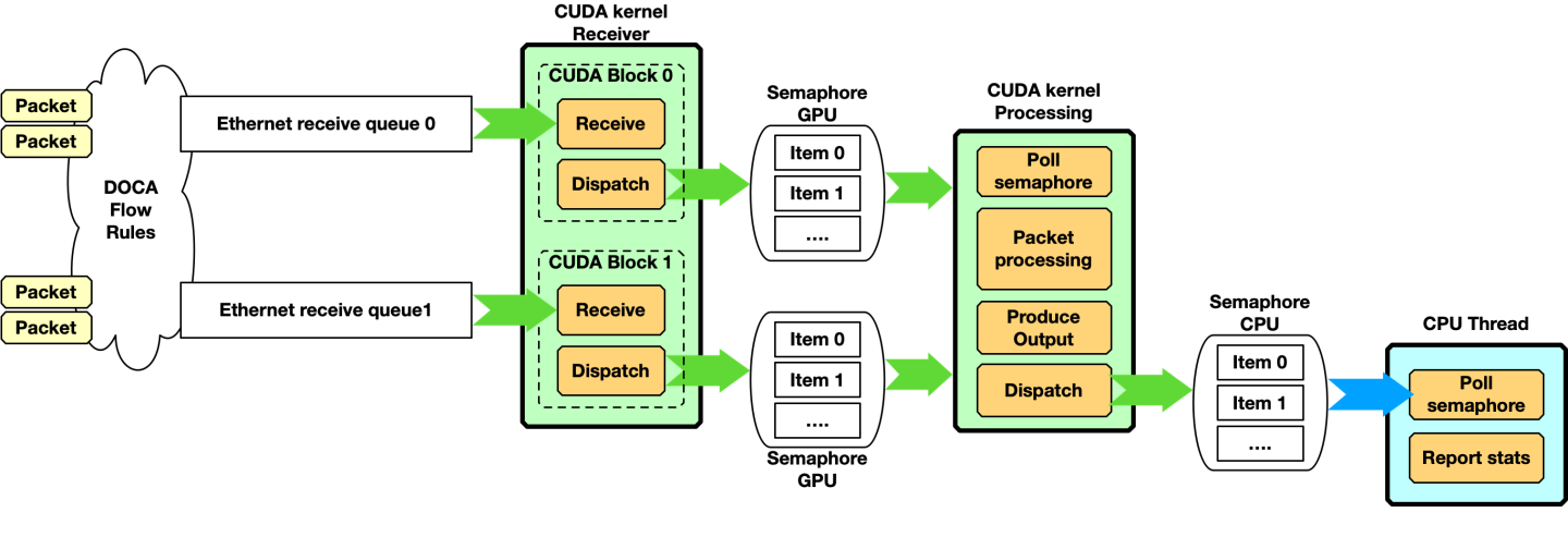
在此示例中,应用程序必须从不同的队列接收数据包,并使用接收器 CUDA 内核将数据包信息分发到负责数据包处理的第二个 CUDA 内核。
CPU 启动 CUDA 内核并等待信号量的输出
CPU 代码
            #define CUDA_THREADS 512
#define CUDA_BLOCKS 1
int semaphore_index = 0;
enum doca_gpu_semaphore_status status;
struct custom_info *gpu_info;

/* On the CPU */
cuda_kernel_receive_dispatch<<<CUDA_THREADS, CUDA_BLOCKS, ..., stream_0>>>(eth_rxq_gpu, sem_to_gpu_gpu)
cuda_kernel_process<<<CUDA_THREADS, CUDA_BLOCKS, ..., stream_1>>>(eth_rxq_gpu, sem_to_cpu_gpu, sem_to_gpu_gpu)

while(/* condition */) {
	doca_gpu_semaphore_get_status(sem_to_cpu, semaphore_index, &status);
	if (status == DOCA_GPU_SEMAPHORE_STATUS_READY) {
		doca_gpu_semaphore_get_custom_info_addr(sem_to_cpu, semaphore_index, (void **)&(gpu_info));
		report_info(gpu_info);
		doca_gpu_semaphore_set_status(sem_to_cpu, semaphore_index, DOCA_GPU_SEMAPHORE_STATUS_FREE);
		semaphore_index = (semaphore_index+1) % SEMAPHORE_ITEMS;
	}
}
在 GPU 上,两个 CUDA 内核在不同的流上运行
GPU 代码
            cuda_kernel_receive_dispatch(eth_rxq_gpu, sem_to_gpu_gpu) {
	__shared__ uint32_t rx_pkt_num;
	__shared__ uint64_t rx_buf_idx;
	int semaphore_index = 0;

	while (/* exit condition */) {
		doca_gpu_dev_eth_rxq_receive_block(eth_rxq_gpu, MAX_NUM_RECEIVE_PACKETS, TIMEOUT_RECEIVE_NS, &rx_pkt_num, &rx_buf_idx);
		if (threadIdx.x == 0 && rx_pkt_num > 0) {
			doca_gpu_dev_sem_set_packet_info(sem_to_gpu_gpu, semaphore_index, DOCA_GPU_SEMAPHORE_STATUS_READY, rx_pkt_num, rx_buf_idx);
			semaphore_index = (semaphore_index+1) % SEMAPHORE_ITEMS;
		}
	}
}

cuda_kernel_process(eth_rxq_gpu, sem_to_cpu_gpu, sem_to_gpu_gpu) {
	__shared__ uint32_t rx_pkt_num;
	__shared__ uint64_t rx_buf_idx;
	int semaphore_index = 0;
	int thread_buf_idx = 0;
	struct doca_gpu_buf *buf_ptr;
	uintptr_t buf_addr;
	struct custom_info *gpu_info;

	while (/* exit condition */) {
		if (threadIdx.x == 0) {
			do {
				result = doca_gpu_dev_sem_get_packet_info_status(sem_to_gpu_gpu, semaphore_index, DOCA_GPU_SEMAPHORE_STATUS_READY, &rx_pkt_num, &rx_buf_idx);
			} while(result != DOCA_ERROR_NOT_FOUND /* && other exit condition */);
		}
		__syncthreads();

		thread_buf_idx = threadIdx.x;
		while (thread_buf_idx < rx_pkt_num) {
			/* Get DOCA GPU buffer from the GPU buffer in the receive queue */
			doca_gpu_dev_eth_rxq_get_buf(eth_rxq_gpu, rx_buf_idx + thread_buf_idx, &buf_ptr);
			/* Get DOCA GPU buffer memory address */
			doca_gpu_dev_buf_get_addr(buf_ptr, &buf_addr);
			/*
			 * Atomic here is has the entire CUDA block accesses the same semaphore to CPU.
			 * Smarter implementation can be done at warp level, with multiple semaphores, etc.. to avoid this atomic
			 */
			int semaphore_index_tmp = atomicAdd_block(&semaphore_index, 1);
			semaphore_index_tmp = semaphore_index_tmp % SEMAPHORE_ITEMS;
			doca_gpu_dev_sem_get_custom_info_addr(sem_to_cpu_gpu, semaphore_index_tmp, (void **)&gpu_info);
			populate_custom_info(buf_addr, gpu_info);
			doca_gpu_dev_sem_set_status(sem_to_cpu_gpu, semaphore_index_tmp, DOCA_GPU_SEMAPHORE_STATUS_READY);
		}
		__syncthreads();

		if (threadIdx.x == 0) {
			doca_gpu_dev_sem_set_status(sem_to_gpu_gpu, semaphore_index, DOCA_GPU_SEMAPHORE_STATUS_READY);
		}
	}
}
当使用多个队列和/或信号量时,可以使用以下图表表示此代码
请注意,接收数据包并将数据包分发到另一个 CUDA 内核不是必需的。更简单的场景可以只有一个 CUDA 内核接收和处理数据包
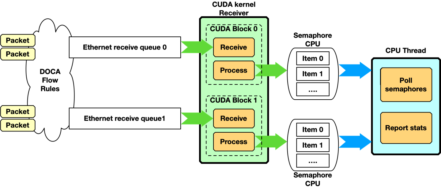
这种方法的缺点是,两次接收之间的时间取决于 CUDA 内核处理接收到的数据包所花费的时间。
必须构建的管道类型在很大程度上取决于具体的用例。
生成和发送
在此示例中,GPU 生成一些数据,将其存储到数据包中,然后通过网络发送这些数据包。CPU 启动 CUDA 内核并继续执行其他工作
CPU 代码
            #define CUDA_THREADS 512
#define CUDA_BLOCKS 1
int semaphore_index = 0;
enum doca_gpu_semaphore_status status;
struct custom_info *gpu_info;

/* On the CPU */
cuda_kernel_produce_send<<<CUDA_THREADS, CUDA_BLOCKS, ..., stream_0>>>(eth_txq_gpu, buf_arr_gpu)

/* do other stuff */
在 GPU 上,CUDA 内核用有意义的数据填充数据包并发送它们。在以下示例中,作用域是 CUDA 块,因此每个块使用不同的 DOCA 以太网发送队列
GPU 代码
            cuda_kernel_produce_send(eth_txq_gpu, buf_arr_gpu) {
	uint64_t doca_gpu_buf_idx = threadIdx.x;
	struct doca_gpu_buf *buf;
	uintptr_t buf_addr;
	uint32_t packet_len;
	uint32_t curr_position;
	uint32_t mask_max_position;
	uint32_t num_pkts_per_send = blockDim.x;

	/* Get last occupied position in the Tx queue */
	doca_gpu_dev_eth_txq_get_info(eth_txq_gpu, &curr_position, &mask_max_position);
	__syncthreads();

	while (/* exit condition */) {
   		/* Each CUDA thread retrieves doca_gpu_buf from doca_gpu_buf_arr */
		doca_gpu_dev_buf_get_buf(buf_arr_gpu, doca_gpu_buf_idx, &buf);
		/* Get memory address of the packet in the doca_gpu_buf */
		doca_gpu_dev_buf_get_addr(buf, &buf_addr);

		/* Application produces data and crafts the packet in the doca_gpu_buf */
		populate_packet(buf_addr, &packet_len);

		/* Enqueue packet in the send queue with weak mode: each thread posts the packet in a different and sequential position of the queue */
		doca_gpu_dev_eth_txq_send_enqueue_weak(eth_txq_gpu, buf, packet_len, ((curr_position + doca_gpu_buf_idx) & mask_max_position), DOCA_GPU_SEND_FLAG_NONE);

		/* Synchronization point */
		__synchthreads();

		/* Only one CUDA thread in the block must commit and push the send queue */
		if (threadIdx.x == 0) {
			doca_gpu_dev_eth_txq_commit_weak(eth_txq_gpu, num_pkts_per_send);
			doca_gpu_dev_eth_txq_push(eth_txq_gpu);
		}
		/* Synchronization point */
		__synchthreads();
		/* Assume all threads in the block pushed a packet in the send queue */
		doca_gpu_buf_idx += blockDim.x;
	}
}
带有 GPU 数据路径的 RDMA 队列
要从 GPU CUDA 内核执行 RDMA 操作,在设置阶段,应用程序必须首先创建 DOCA RDMA 队列,将 RDMA 导出为上下文,然后在 GPU 上设置上下文的数据路径(如下面的代码片段所示)。
以下是作为指南的伪代码。有关函数的完整概述,请参阅头文件 (*.h) 中的实际函数签名和文档。
GPU 代码
            struct doca_dev *doca_device;	    /* DOCA device */
struct doca_gpu *gpudev;	    /* DOCA GPU device */
struct doca_rdma *rdma;		    /* DOCA RDMA instance */
struct doca_gpu_dev_rdma *gpu_rdma; /* DOCA RDMA instance GPU handler */
struct doca_ctx *rdma_ctx;

// Initialize IBDev RDMA device
open_doca_device_with_ibdev_name(&doca_device)

// Initialize the GPU device
doca_gpu_create(&gpudev);
// Create the RDMA queue object with the DOCA device
doca_rdma_create(doca_device, &(rdma));
// Export the RDMA queue object context
rdma_ctx = doca_rdma_as_ctx(rdma)

// Set RDMA queue attributes

// Set GPU data path for the RDMA object
doca_ctx_set_datapath_on_gpu(ctx, gpudev)
doca_ctx_start(rdma_ctx);
此时,应用程序具有可从 GPU CUDA 内核使用的 RDMA 队列。下一步将是使用一些 OOB(带外)机制(例如,Linux 套接字)建立连接,以交换 RDMA 队列信息,以便每个对等方都可以连接到另一个对等方的队列。
为了交换数据,用户必须创建 DOCA GPU 缓冲区数组来发送或接收数据。如果应用程序还需要读取或写入,则必须导出与缓冲区数组关联的 GPU 内存,并使用 OOB 机制与远程对等方交换。
GPU 代码
            /* Create DOCA mmap to define memory layout and type for the DOCA buf array */
struct doca_mmap *mmap;
doca_mmap_create(&mmap);
/* Set DOCA mmap properties */
doca_mmap_start(mmap);
/* Export mmap info to share with remote peer */
doca_mmap_export_rdma(mmap, ...);

/* Exchange export info with remote peer */

/* Create DOCA buf arr and export it to GPU */
struct doca_buf_arr *buf_arr;
struct doca_gpu_buf_arr *buf_arr_gpu;
doca_buf_arr_create(mmap, &buf_arr);
/* Set DOCA buf array properties */
...
/* Export GPU handle for the buf arr */
doca_buf_arr_get_gpu_handle(buf_arr, &buf_arr_gpu);
请参阅 “RDMA 客户端服务器” 示例,作为实现本节中描述的所有步骤的基本布局。
用于 RDMA 写入的 CUDA 内核
假设 RDMA 队列和缓冲区数组已正确创建并在对等方之间交换,则应用程序可以启动 CUDA 内核以远程写入数据。由于通常应用程序使用 strong 模式,因此以下代码片段显示了如何使用 weak 模式从同一 CUDA 块中的不同 CUDA 线程发布多个写入。
GPU 代码
            __global__ void rdma_write_bw(struct doca_gpu_dev_rdma *rdma_gpu, struct doca_gpu_buf_arr *local_buf_arr, struct doca_gpu_buf_arr *remote_buf_arr)
{
	struct doca_gpu_buf *remote_buf;
	struct doca_gpu_buf *local_buf;
	struct doca_gpu_dev_rdma *rdma_gpu;
	struct doca_gpu_buf_arr *server_local_buf_arr;
	struct doca_gpu_buf_arr *server_remote_buf_arr;
	uint32_t curr_position;
	uint32_t mask_max_position;
	uint32_t num_ops;

	doca_gpu_dev_buf_get_buf(server_local_buf_arr, threadIdx.x, &local_buf);
	doca_gpu_dev_buf_get_buf(server_remote_buf_arr, threadIdx.x, &remote_buf);
	/* Get RDMA queue current available position and mask of the max position number */
	doca_gpu_dev_rdma_get_info(rdma_gpu, &curr_position, &mask_max_position);

	doca_gpu_dev_rdma_write_weak(rdma_gpu,
					/* Write into this remote buffer at offset 0 */
					remote_buf, 0,
 					/* Fetch data from this local buffer at offset 0 */
					local_buf, 0,
					/* Number of bytes to write */
					msg_size,
					/* Don't use immediate */
					0, DOCA_GPU_RDMA_WRITE_FLAG_NONE,
					/* Position in the RDMA queue to post the write */
					(curr_position + threadIdx.x) & mask_max_position);

		/* Wait all CUDA threads to post their RDMA Write */
		__syncthreads();

		if (threadIdx.x == 0) {
			/* Only 1 CUDA thread can push the write op just posted */
			doca_gpu_dev_rdma_commit_weak(rdma_gpu, blockDim.x);
			doca_gpu_dev_rdma_wait_all(rdma_gpu, &num_ops);
		}
		__syncthreads();
}
“RDMA 客户端服务器” 示例中的代码显示了如何使用写入和带立即数标志设置的发送。
本节包含两个示例,展示了如何启用简单的 GPUNetIO 功能。请务必正确设置以下环境变量
构建示例
            export PATH=${PATH}:/usr/local/cuda/bin
export CPATH="$(echo /usr/local/cuda/targets/{x86_64,sbsa}-linux/include | sed 's/ /:/'):${CPATH}"
export PKG_CONFIG_PATH=${PKG_CONFIG_PATH}:/usr/lib/pkgconfig:/opt/mellanox/grpc/lib/{x86_64,aarch64}-linux-gnu/pkgconfig:/opt/mellanox/dpdk/lib/{x86_64,aarch64}-linux-gnu/pkgconfig:/opt/mellanox/doca/lib/{x86_64,aarch64}-linux-gnu/pkgconfigexport LD_LIBRARY_PATH=${LD_LIBRARY_PATH}:/usr/local/cuda/lib64:/opt/mellanox/gdrcopy/src:/opt/mellanox/dpdk/lib/{x86_64,aarch64}-linux-gnu:/opt/mellanox/doca/lib/{x86_64,aarch64}-linux-gnu
本节中描述的所有 DOCA 示例均受 BSD-3 软件许可协议管辖。
在构建示例之前,请确保 GPU 的架构已包含在 meson.build 文件中(例如,Ampere 的 sm_80,L40 的 sm_89,H100 的 sm_90 等)。
以太网发送等待时间
该示例展示了如何在 GPUNetIO 应用程序的上下文中启用精确发送调度(或 wait-on-time)。精确发送调度是 NVIDIA NIC 根据应用程序提供的时间戳在未来发送数据包的能力。
ConnectX-6 Dx 及更高版本支持此功能。
这篇 NVIDIA 博客文章 提供了一个示例,说明此功能如何在 5G 网络中使用。
此 DOCA GPUNetIO 示例提供了一个简单的应用程序,用于从 GPU 以精确发送调度方式发送数据包。
时钟同步
在启动示例之前,务必正确同步 CPU 时钟和 NIC 时钟。这样,系统时钟提供的时间戳将与 NIC 中的时间同步。
为此,至少必须使用 phc2sys 服务。要在 Ubuntu 系统上安装它
phc2sys
sudo apt install linuxptp
要正确启动 phc2sys 服务,必须在 /lib/systemd/system/phc2sys.service 中创建一个配置文件
phc2sys
            [Unit]
Description=Synchronize system clock or PTP hardware clock (PHC)
Documentation=man:phc2sys

[Service]
Restart=always
RestartSec=5s
Type=simple
ExecStart=/bin/sh -c "taskset -c 15 /usr/sbin/phc2sys -s /dev/ptp$(ethtool -T ens6f0 | grep PTP | awk '{print $4}') -c CLOCK_REALTIME -n 24 -O 0 -R 256 -u 256"

[Install]
WantedBy=multi-user.target
现在可以启动 phc2sys 服务了
phc2sys
            sudo systemctl stop systemd-timesyncd
sudo systemctl disable systemd-timesyncd
sudo systemctl daemon-reload
sudo systemctl start phc2sys.service
要检查 phc2sys 的状态
phc2sys
            $ sudo systemctl status phc2sys.service

● phc2sys.service - Synchronize system clock or PTP hardware clock (PHC)
     Loaded: loaded (/lib/systemd/system/phc2sys.service; disabled; vendor preset: enabled)
     Active: active (running) since Mon 2023-04-03 10:59:13 UTC; 2 days ago
       Docs: man:phc2sys
   Main PID: 337824 (sh)
      Tasks: 2 (limit: 303788)
     Memory: 560.0K
        CPU: 52min 8.199s
     CGroup: /system.slice/phc2sys.service
             ├─337824 /bin/sh -c "taskset -c 15 /usr/sbin/phc2sys -s /dev/ptp\$(ethtool -T enp23s0f1np1 | grep PTP | awk '{print \$4}') -c CLOCK_REALTIME -n 24 -O 0 -R >
             └─337829 /usr/sbin/phc2sys -s /dev/ptp3 -c CLOCK_REALTIME -n 24 -O 0 -R 256 -u 256

Apr 05 16:35:52 doca-vr-045 phc2sys[337829]: [457395.040] CLOCK_REALTIME rms    8 max   18 freq +110532 +/-  27 delay   770 +/-   3
Apr 05 16:35:53 doca-vr-045 phc2sys[337829]: [457396.071] CLOCK_REALTIME rms    8 max   20 freq +110513 +/-  30 delay   769 +/-   3
Apr 05 16:35:54 doca-vr-045 phc2sys[337829]: [457397.102] CLOCK_REALTIME rms    8 max   18 freq +110527 +/-  30 delay   769 +/-   3
Apr 05 16:35:55 doca-vr-045 phc2sys[337829]: [457398.130] CLOCK_REALTIME rms    8 max   18 freq +110517 +/-  31 delay   769 +/-   3
Apr 05 16:35:56 doca-vr-045 phc2sys[337829]: [457399.159] CLOCK_REALTIME rms    8 max   19 freq +110523 +/-  32 delay   770 +/-   3
Apr 05 16:35:57 doca-vr-045 phc2sys[337829]: [457400.191] CLOCK_REALTIME rms    8 max   20 freq +110528 +/-  33 delay   770 +/-   3
Apr 05 16:35:58 doca-vr-045 phc2sys[337829]: [457401.221] CLOCK_REALTIME rms    8 max   19 freq +110512 +/-  38 delay   770 +/-   3
Apr 05 16:35:59 doca-vr-045 phc2sys[337829]: [457402.253] CLOCK_REALTIME rms    9 max   20 freq +110538 +/-  47 delay   770 +/-   4
Apr 05 16:36:00 doca-vr-045 phc2sys[337829]: [457403.281] CLOCK_REALTIME rms    8 max   21 freq +110517 +/-  38 delay   769 +/-   3
Apr 05 16:36:01 doca-vr-045 phc2sys[337829]: [457404.311] CLOCK_REALTIME rms    8 max   17 freq +110526 +/-  26 delay   769 +/-   3
...
此时,系统和 NIC 时钟已同步,因此 CPU 提供的时间戳可以被 NIC 正确解释。
您获取的时间戳可能无法反映真实时间和日期。要获取真实时间和日期,您必须使用系统上的外部主时钟正确设置 ptp4l 服务。执行此操作不在本示例的范围之内。
运行示例
该示例随附了必须构建的源文件
phc2sys
            # Ensure DOCA and DPDK are in the pkgconfig environment variable
cd /opt/mellanox/doca/samples/doca_gpunetio/gpunetio_send_wait_time
meson build
ninja -C build
该示例以定时方式向虚拟以太网地址 10:11:12:13:14:15 发送 8 个突发的 32 个原始以太网数据包或 1kB 数据包。将 NIC 编程为每 t 纳秒发送一次(命令行选项 -t)。
以下示例将 GPU PCIe 地址为 ca:00.0 和 NIC PCIe 地址为 17:00.0 的系统编程为每 5 毫秒发送 32 个数据包
运行
            # Ensure DOCA and DPDK are in the LD_LIBRARY_PATH environment variable
$ sudo ./build/doca_gpunetio_send_wait_time -n 17:00.0 -g ca:00.0 -t 5000000[09:22:54:165778][1316878][DOCA][INF][gpunetio_send_wait_time_main.c:195][main] Starting the sample
[09:22:54:438260][1316878][DOCA][INF][gpunetio_send_wait_time_main.c:224][main] Sample configuration:
		GPU ca:00.0
		NIC 17:00.0
		Timeout 5000000ns
EAL: Detected CPU lcores: 128
...
EAL: Probe PCI driver: mlx5_pci (15b3:a2d6) device: 0000:17:00.0 (socket 0)
[09:22:54:819996][1316878][DOCA][INF][gpunetio_send_wait_time_sample.c:607][gpunetio_send_wait_time] Wait on time supported mode: DPDK
EAL: Probe PCI driver: gpu_cuda (10de:20b5) device: 0000:ca:00.0 (socket 1)
[09:22:54:830212][1316878][DOCA][INF][gpunetio_send_wait_time_sample.c:252][create_tx_buf] Mapping send queue buffer (0x0x7f48e32a0000 size 262144B) with legacy nvidia-peermem mode
[09:22:54:832462][1316878][DOCA][INF][gpunetio_send_wait_time_sample.c:657][gpunetio_send_wait_time] Launching CUDA kernel to send packets
[09:22:54:842945][1316878][DOCA][INF][gpunetio_send_wait_time_sample.c:664][gpunetio_send_wait_time] Waiting 10 sec for 256 packets to be sent
[09:23:04:883309][1316878][DOCA][INF][gpunetio_send_wait_time_sample.c:684][gpunetio_send_wait_time] Sample finished successfully
[09:23:04:883339][1316878][DOCA][INF][gpunetio_send_wait_time_main.c:239][main] Sample finished successfully
要验证数据包是否在正确的时间实际发送,请在另一侧使用数据包嗅探器(例如,tcpdump)
phc2sys
            $ sudo tcpdump -i enp23s0f1np1 -A -s 64

17:12:23.480318 IP5 (invalid)
Sent from DOCA GPUNetIO...........................
....
17:12:23.480368 IP5 (invalid)
Sent from DOCA GPUNetIO...........................
# end of first burst of 32 packets, bump to +5ms
17:12:23.485321 IP5 (invalid)
Sent from DOCA GPUNetIO...........................
...
17:12:23.485369 IP5 (invalid)
Sent from DOCA GPUNetIO...........................
# end of second burst of 32 packets, bump to +5ms
17:12:23.490278 IP5 (invalid)
Sent from DOCA GPUNetIO...........................
...
输出应显示每 32 个数据包大约跳跃 5 毫秒。
tcpdump 可能会增加嗅探数据包和报告接收时间戳的延迟,因此报告的每 32 个数据包突发之间的差异可能小于预期,尤其是在间隔时间较小(例如 500 微秒 (-t 500000))的情况下。
以太网简单接收
这个简单的应用程序展示了构建 DOCA GPUNetIO 接收器应用程序的基本步骤,该应用程序具有一个用于 UDP 数据包的队列和一个 CUDA 内核,用于从 GPU 接收这些数据包,并将数据包信息打印到控制台。
从 CUDA 内核调用 printf 对于发布软件来说不是好的做法,应该仅用于打印调试信息,因为它会降低 CUDA 内核的整体执行速度。
构建和运行应用程序
构建示例
            # Ensure DOCA and DPDK are in the pkgconfig environment variable
cd /opt/mellanox/doca/samples/doca_gpunetio/gpunetio_simple_receive
meson build
ninja -C build
为了测试应用程序,本指南假设通常的设置是使用两台机器:一台运行 DOCA 接收器应用程序,另一台充当数据包生成器。作为 UDP 数据包生成器,此示例考虑了 nping 应用程序,该应用程序可以轻松地安装在任何 Linux 机器上。
在数据包生成器机器上通过 nping 发送 10 个 UDP 数据包的命令是
nping 生成器
            $ nping --udp -c 10 -p 2090 192.168.1.1 --data-length 1024 --delay 500ms

Starting Nping 0.7.80 ( https://nmap.org/nping ) at 2023-11-20 11:05 UTC
SENT (0.0018s) UDP packet with 1024 bytes to 192.168.1.1:2090
SENT (0.5018s) UDP packet with 1024 bytes to 192.168.1.1:2090
SENT (1.0025s) UDP packet with 1024 bytes to 192.168.1.1:2090
SENT (1.5025s) UDP packet with 1024 bytes to 192.168.1.1:2090
SENT (2.0032s) UDP packet with 1024 bytes to 192.168.1.1:2090
SENT (2.5033s) UDP packet with 1024 bytes to 192.168.1.1:2090
SENT (3.0040s) UDP packet with 1024 bytes to 192.168.1.1:2090
SENT (3.5040s) UDP packet with 1024 bytes to 192.168.1.1:2090
SENT (4.0047s) UDP packet with 1024 bytes to 192.168.1.1:2090
SENT (4.5048s) UDP packet with 1024 bytes to 192.168.1.1:2090

Max rtt: N/A | Min rtt: N/A | Avg rtt: N/A
UDP packets sent: 10 | Rcvd: 0 | Lost: 10 (100.00%)
Nping done: 1 IP address pinged in 5.50 seconds
假设 DOCA Simple Receive 示例正在另一台 IP 地址为 192.168.1.1 的机器上等待。
DOCA Simple Receive 示例在 NIC 的 PCIe 地址为 17:00.1,GPU 的 PCIe 地址为 ca:00.0 的系统上启动
DOCA Simple Receive
            # Ensure DOCA and DPDK are in the LD_LIBRARY_PATH environment variable
$ sudo ./build/doca_gpunetio_simple_receive -n 17:00.1 -g ca:00.0
[11:00:30:397080][2328673][DOCA][INF][gpunetio_simple_receive_main.c:159][main] Starting the sample
[11:00:30:652622][2328673][DOCA][INF][gpunetio_simple_receive_main.c:189][main] Sample configuration:
	GPU ca:00.0
	NIC 17:00.1

EAL: Detected CPU lcores: 128
EAL: Detected NUMA nodes: 2
EAL: Detected shared linkage of DPDK
EAL: Multi-process socket /var/run/dpdk/rte/mp_socket
EAL: Selected IOVA mode 'PA'
EAL: VFIO support initialized
TELEMETRY: No legacy callbacks, legacy socket not created
EAL: Probe PCI driver: mlx5_pci (15b3:a2d6) device: 0000:17:00.1 (socket 0)
[11:00:31:036760][2328673][DOCA][WRN][engine_model.c:72][adapt_queue_depth] adapting queue depth to 128.
[11:00:31:928926][2328673][DOCA][WRN][engine_port.c:321][port_driver_process_properties] detected representor used in VNF mode (driver port id 0)
EAL: Probe PCI driver: gpu_cuda (10de:20b5) device: 0000:ca:00.0 (socket 1)
[11:00:31:977261][2328673][DOCA][INF][gpunetio_simple_receive_sample.c:425][create_rxq] Creating Sample Eth Rxq

[11:00:31:977841][2328673][DOCA][INF][gpunetio_simple_receive_sample.c:466][create_rxq] Mapping receive queue buffer (0x0x7f86cc000000 size 33554432B) with nvidia-peermem mode
[11:00:32:043182][2328673][DOCA][INF][gpunetio_simple_receive_sample.c:610][gpunetio_simple_receive] Launching CUDA kernel to receive packets
[11:00:32:055193][2328673][DOCA][INF][gpunetio_simple_receive_sample.c:614][gpunetio_simple_receive] Waiting for termination
Thread 0 received UDP packet with Eth src 10:70:fd:fa:77:f5 - Eth dst 10:70:fd:fa:77:e9
Thread 0 received UDP packet with Eth src 10:70:fd:fa:77:f5 - Eth dst 10:70:fd:fa:77:e9
Thread 0 received UDP packet with Eth src 10:70:fd:fa:77:f5 - Eth dst 10:70:fd:fa:77:e9
Thread 0 received UDP packet with Eth src 10:70:fd:fa:77:f5 - Eth dst 10:70:fd:fa:77:e9
Thread 0 received UDP packet with Eth src 10:70:fd:fa:77:f5 - Eth dst 10:70:fd:fa:77:e9
Thread 0 received UDP packet with Eth src 10:70:fd:fa:77:f5 - Eth dst 10:70:fd:fa:77:e9
Thread 0 received UDP packet with Eth src 10:70:fd:fa:77:f5 - Eth dst 10:70:fd:fa:77:e9
Thread 0 received UDP packet with Eth src 10:70:fd:fa:77:f5 - Eth dst 10:70:fd:fa:77:e9
Thread 0 received UDP packet with Eth src 10:70:fd:fa:77:f5 - Eth dst 10:70:fd:fa:77:e9
Thread 0 received UDP packet with Eth src 10:70:fd:fa:77:f5 - Eth dst 10:70:fd:fa:77:e9

# Type Ctrl+C to kill the sample

[11:01:44:265141][2328673][DOCA][INF][gpunetio_simple_receive_sample.c:45][signal_handler] Signal 2 received, preparing to exit!
[11:01:44:265189][2328673][DOCA][INF][gpunetio_simple_receive_sample.c:620][gpunetio_simple_receive] Exiting from sample
[11:01:44:265533][2328673][DOCA][INF][gpunetio_simple_receive_sample.c:362][destroy_rxq] Destroying Rxq
[11:01:44:307829][2328673][DOCA][INF][gpunetio_simple_receive_sample.c:631][gpunetio_simple_receive] Sample finished successfully
[11:01:44:307861][2328673][DOCA][INF][gpunetio_simple_receive_main.c:204][main] Sample finished successfully
RDMA 客户端服务器
此示例展示了如何使用 GPUNetIO RDMA API 来接收和发送/写入(使用立即数),方法是使用单个 RDMA 队列。
服务器具有一个 GPU 缓冲区数组 A,由 GPU_BUF_NUM doca_gpu_buf 元素组成,每个元素的大小为 1kB。客户端具有两个 GPU 缓冲区数组 B 和 C,每个数组由 GPU_BUF_NUM doca_gpu_buf 元素组成,每个元素的大小为 512B。
目标是让客户端使用两个 512B 的 GPU 缓冲区填充服务器的单个 1kB 缓冲区,如下图所示

为了展示如何使用 RDMA 写入和发送,偶数缓冲区通过写入立即数发送,而奇数缓冲区通过发送立即数发送。在这两种情况下,服务器都必须预先发布 RDMA 接收操作。
对于每个缓冲区,CUDA 内核代码都会重复握手
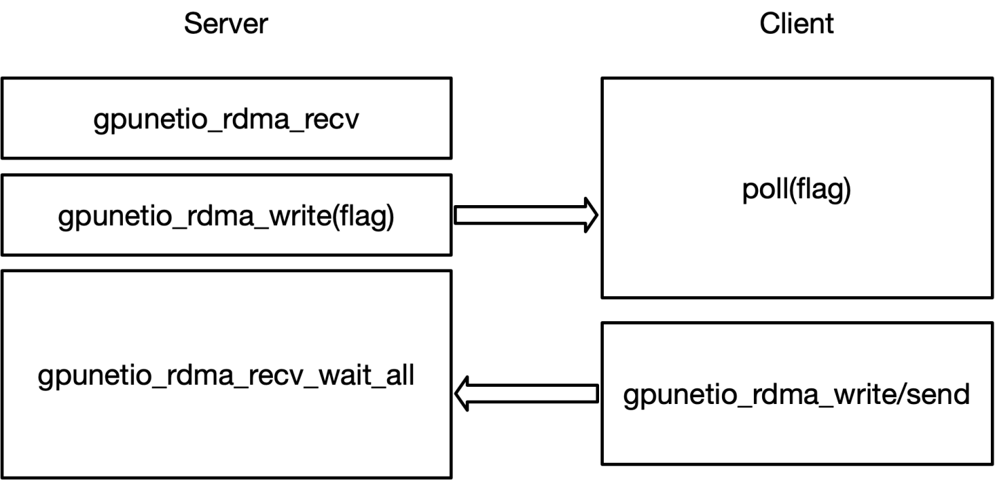
填充所有缓冲区后,服务器将仔细检查所有值是否有效。服务器输出应如下所示
DOCA RDMA 服务器端
            # Ensure DOCA and DPDK are in the LD_LIBRARY_PATH environment variable
$ cd /opt/mellanox/doca/samples/doca_gpunetio/gpunetio_rdma_client_server_write
$ ./build/doca_gpunetio_rdma_client_server_write -gpu 17:00.0 -d mlx5_0

[14:11:43:000930][1173110][DOCA][INF][gpunetio_rdma_client_server_write_main.c:250][main] Starting the sample
...
[14:11:43:686610][1173110][DOCA][INF][rdma_common.c:91][oob_connection_server_setup] Listening for incoming connections
[14:11:45:681523][1173110][DOCA][INF][rdma_common.c:105][oob_connection_server_setup] Client connected at IP: 192.168.2.28 and port: 46274
...
[14:11:45:771807][1173110][DOCA][INF][gpunetio_rdma_client_server_write_sample.c:644][rdma_write_server] Before launching CUDA kernel, buffer array A is:
[14:11:45:771822][1173110][DOCA][INF][gpunetio_rdma_client_server_write_sample.c:646][rdma_write_server] Buffer 0 -> offset 0: 1111 | offset 128: 1111
[14:11:45:771837][1173110][DOCA][INF][gpunetio_rdma_client_server_write_sample.c:646][rdma_write_server] Buffer 1 -> offset 0: 1111 | offset 128: 1111
[14:11:45:771851][1173110][DOCA][INF][gpunetio_rdma_client_server_write_sample.c:646][rdma_write_server] Buffer 2 -> offset 0: 1111 | offset 128: 1111
[14:11:45:771864][1173110][DOCA][INF][gpunetio_rdma_client_server_write_sample.c:646][rdma_write_server] Buffer 3 -> offset 0: 1111 | offset 128: 1111
RDMA Recv 2 ops completed with immediate values 0 and 1!
RDMA Recv 2 ops completed with immediate values 1 and 2!
RDMA Recv 2 ops completed with immediate values 2 and 3!
RDMA Recv 2 ops completed with immediate values 3 and 4!
[14:11:45:781561][1173110][DOCA][INF][gpunetio_rdma_client_server_write_sample.c:671][rdma_write_server] After launching CUDA kernel, buffer array A is:
[14:11:45:781574][1173110][DOCA][INF][gpunetio_rdma_client_server_write_sample.c:673][rdma_write_server] Buffer 0 -> offset 0: 2222 | offset 128: 3333
[14:11:45:781583][1173110][DOCA][INF][gpunetio_rdma_client_server_write_sample.c:673][rdma_write_server] Buffer 1 -> offset 0: 2222 | offset 128: 3333
[14:11:45:781593][1173110][DOCA][INF][gpunetio_rdma_client_server_write_sample.c:673][rdma_write_server] Buffer 2 -> offset 0: 2222 | offset 128: 3333
[14:11:45:781602][1173110][DOCA][INF][gpunetio_rdma_client_server_write_sample.c:673][rdma_write_server] Buffer 3 -> offset 0: 2222 | offset 128: 3333
[14:11:45:781640][1173110][DOCA][INF][gpunetio_rdma_client_server_write_main.c:294][main] Sample finished successfully
在另一侧,假设服务器的 IP 地址为 192.168.2.28,则客户端输出应如下所示
DOCA RDMA 客户端
            # Ensure DOCA and DPDK are in the LD_LIBRARY_PATH environment variable

$ cd /opt/mellanox/doca/samples/doca_gpunetio/gpunetio_rdma_client_server_write
$ ./build/doca_gpunetio_rdma_client_server_write -gpu 17:00.0 -d mlx5_0 -c 192.168.2.28

[16:08:22:335744][160913][DOCA][INF][gpunetio_rdma_client_server_write_main.c:197][main] Starting the sample
...
[16:08:25:753316][160913][DOCA][INF][rdma_common.c:147][oob_connection_client_setup] Connected with server successfully
......
Client waiting on flag 7f6596735000 for server to post RDMA Recvs
Thread 0 post rdma write imm 0
Thread 1 post rdma write imm 0
Client waiting on flag 7f6596735001 for server to post RDMA Recvs
Thread 0 post rdma send imm 1
Thread 1 post rdma send imm 1
Client waiting on flag 7f6596735002 for server to post RDMA Recvs
Thread 0 post rdma write imm 2
Thread 1 post rdma write imm 2
Client waiting on flag 7f6596735003 for server to post RDMA Recvs
Thread 0 post rdma send imm 3
Thread 1 post rdma send imm 3
[16:08:25:853454][160913][DOCA][INF][gpunetio_rdma_client_server_write_main.c:241][main] Sample finished successfully
对于 RDMA,必须按名称(例如,mlx5_0)而不是 PCIe 地址(以太网的情况)指定网络设备。
也可以启用 RDMA CM 模式,使用相同的 RDMA GPU 句柄建立两个连接。客户端的示例
带 CM 的 DOCA RDMA 客户端
            # Ensure DOCA and DPDK are in the LD_LIBRARY_PATH environment variable

$ cd /opt/mellanox/doca/samples/doca_gpunetio/gpunetio_rdma_client_server_write
$ ./build/samples/doca_gpunetio_rdma_client_server_write -d mlx5_0 -gpu 17:00.0 -gid 3 -c 10.137.189.28 -cm --server-addr-type ipv4 --server-addr 192.168.2.28

[11:30:34:489781][3853018][DOCA][INF][gpunetio_rdma_client_server_write_main.c:461][main] Starting the sample
...
[11:30:35:038828][3853018][DOCA][INF][gpunetio_rdma_client_server_write_sample.c:950][rdma_write_client] Client is waiting for a connection establishment
[11:30:35:082039][3853018][DOCA][INF][gpunetio_rdma_client_server_write_sample.c:963][rdma_write_client] Client - Connection 1 is established
...
[11:30:35:095282][3853018][DOCA][INF][gpunetio_rdma_client_server_write_sample.c:1006][rdma_write_client] Establishing connection 2..
[11:30:35:097521][3853018][DOCA][INF][gpunetio_rdma_client_server_write_sample.c:1016][rdma_write_client] Client is waiting for a connection establishment
[11:30:35:102718][3853018][DOCA][INF][gpunetio_rdma_client_server_write_sample.c:1029][rdma_write_client] Client - Connection 2 is established
[11:30:35:102783][3853018][DOCA][INF][gpunetio_rdma_client_server_write_sample.c:1046][rdma_write_client] Client, terminate kernels
Client waiting on flag 7f16067b5000 for server to post RDMA Recvs
Thread 0 post rdma write imm 0
Thread 1 post rdma write imm 1
Client waiting on flag 7f16067b5001 for server to post RDMA Recvs
Thread 0 post rdma send imm 1
Thread 1 post rdma send imm 2
Client waiting on flag 7f16067b5002 for server to post RDMA Recvs
Thread 0 post rdma write imm 2
Thread 1 post rdma write imm 3
Client waiting on flag 7f16067b5003 for server to post RDMA Recvs
Thread 0 post rdma send imm 3
Thread 1 post rdma send imm 4
Client posted and completed 4 RDMA commits on connection 0. Waiting on the exit flag.
Client waiting on flag 7f16067b5000 for server to post RDMA Recvs
Thread 0 post rdma write imm 0
Thread 1 post rdma write imm 1
Client waiting on flag 7f16067b5001 for server to post RDMA Recvs
Thread 0 post rdma send imm 1
Thread 1 post rdma send imm 2
Client waiting on flag 7f16067b5002 for server to post RDMA Recvs
Thread 0 post rdma write imm 2
Thread 1 post rdma write imm 3
Client waiting on flag 7f16067b5003 for server to post RDMA Recvs
Thread 0 post rdma send imm 3
Thread 1 post rdma send imm 4
Client posted and completed 4 RDMA commits on connection 1. Waiting on the exit flag.
[11:30:35:122448][3853018][DOCA][INF][gpunetio_rdma_client_server_write_main.c:512][main] Sample finished successfully
在 RDMA CM 的情况下,必须在服务器端指定命令选项 -cm。
从 CUDA 内核打印输出不建议用于提高性能。对于调试目的以及像这样的简单示例,这可能是有意义的。
GPU DMA 复制
此示例展示了如何使用 DOCA DMA 和 DOCA GPUNetIO 库从 CPU 到 GPU(使用 DOCA DMA CPU 函数)以及从 GPU 到 CPU(使用 CUDA 内核中的 DOCA GPUNetIO DMA 设备函数)DMA 复制内存缓冲区。此示例需要 DPU,因为它使用 DPU 上的 DMA 引擎。
DOCA RDMA 客户端
            $ cd /opt/mellanox/doca/samples/doca_gpunetio/gpunetio_dma_memcpy

# Build the sample and then execute

$ ./build/doca_gpunetio_dma_memcpy -g 17:00.0 -n ca:00.0
[15:44:04:189462][862197][DOCA][INF][gpunetio_dma_memcpy_main.c:164][main] Starting the sample
EAL: Detected CPU lcores: 64
EAL: Detected NUMA nodes: 2
EAL: Detected shared linkage of DPDK
EAL: Selected IOVA mode 'VA'
EAL: No free 2048 kB hugepages reported on node 0
EAL: No free 2048 kB hugepages reported on node 1
EAL: VFIO support initialized
TELEMETRY: No legacy callbacks, legacy socket not created
EAL: Probe PCI driver: gpu_cuda (10de:2331) device: 0000:17:00.0 (socket 0)
[15:44:04:857251][862197][DOCA][INF][gpunetio_dma_memcpy_sample.c:211][init_sample_mem_objs] The CPU source buffer value to be copied to GPU memory: This is a sample piece of text from CPU
[15:44:04:857359][862197][DOCA][WRN][doca_mmap.cpp:1743][doca_mmap_set_memrange] Mmap 0x55aec6206140: Memory range isn't cache-line aligned - addr=0x55aec52ceb10. For best performance align address to 64B
[15:44:04:858839][862197][DOCA][INF][gpunetio_dma_memcpy_sample.c:158][init_sample_mem_objs] The GPU source buffer value to be copied to CPU memory: This is a sample piece of text from GPU
[15:44:04:921702][862197][DOCA][INF][gpunetio_dma_memcpy_sample.c:570][submit_dma_memcpy_task] Success, DMA memcpy job done successfully
CUDA KERNEL INFO: The GPU destination buffer value after the memcpy: This is a sample piece of text from CPU
CPU received message from GPU: This is a sample piece of text from GPU
[15:44:04:930087][862197][DOCA][INF][gpunetio_dma_memcpy_sample.c:364][gpu_dma_cleanup] Cleanup DMA ctx with GPU data path
[15:44:04:932658][862197][DOCA][INF][gpunetio_dma_memcpy_sample.c:404][gpu_dma_cleanup] Cleanup DMA ctx with CPU data path
[15:44:04:954156][862197][DOCA][INF][gpunetio_dma_memcpy_main.c:197][main] Sample finished successfully