第 2 部分。配置网络硬件#
注意
请参考 NVIDIA SDK Manager 资源,了解 ARC-OTA 的设置和安装。
网络硬件配置步骤如下。
设置主时钟
设置交换机
设置 PTP
设置富士康 O-RU
第 2.1 章 设置 Qulsar 主时钟#
步骤 1。#
请按照 Qulsar 用户指南 设置 MGMT 连接。
步骤 2。#
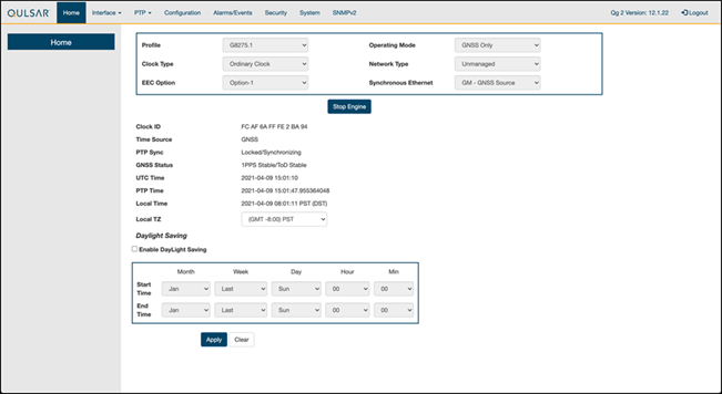
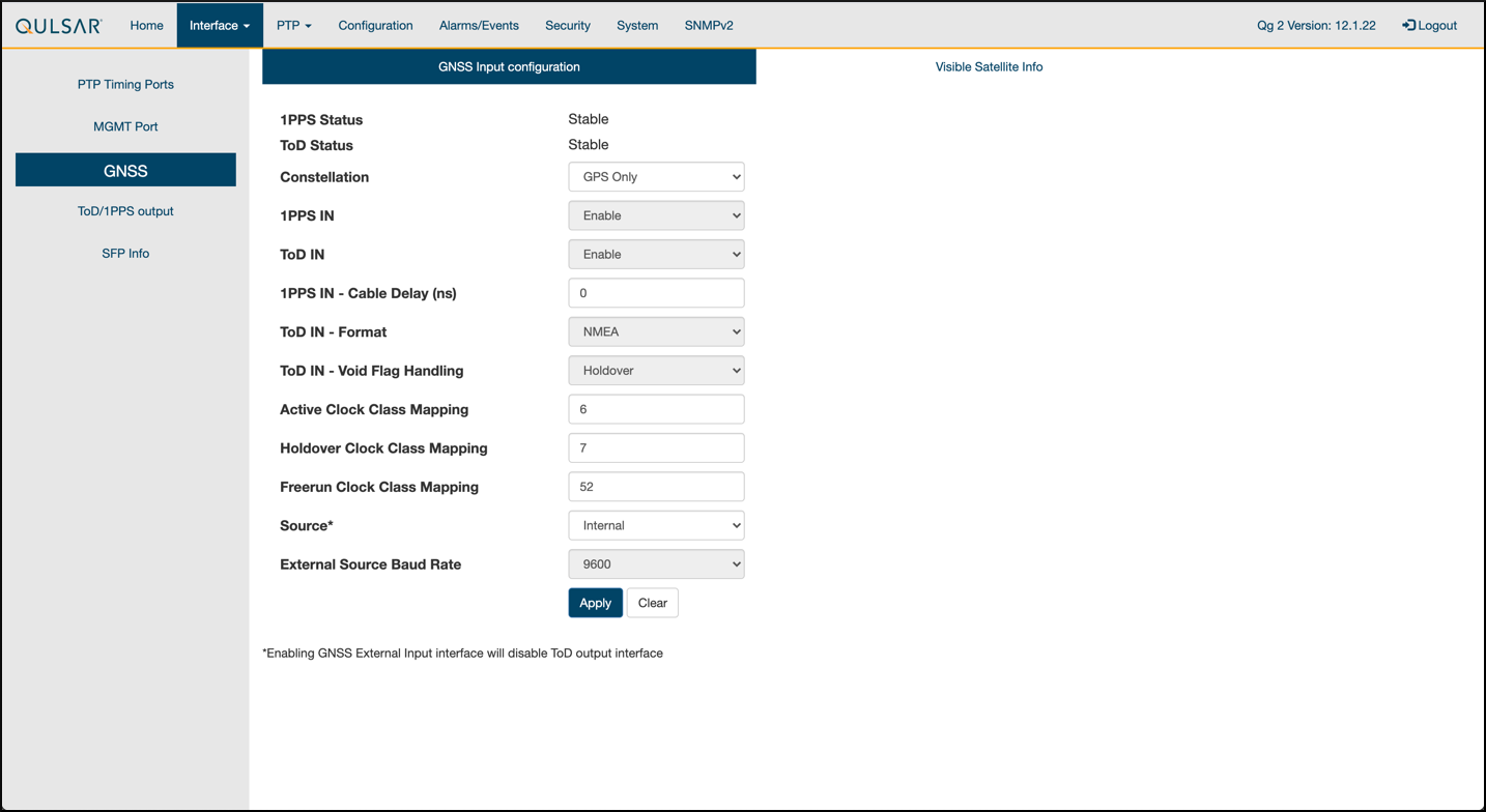
将运行模式设置为 仅 GNSS,并相应设置其他字段,然后运行 启动引擎。
步骤 3。#
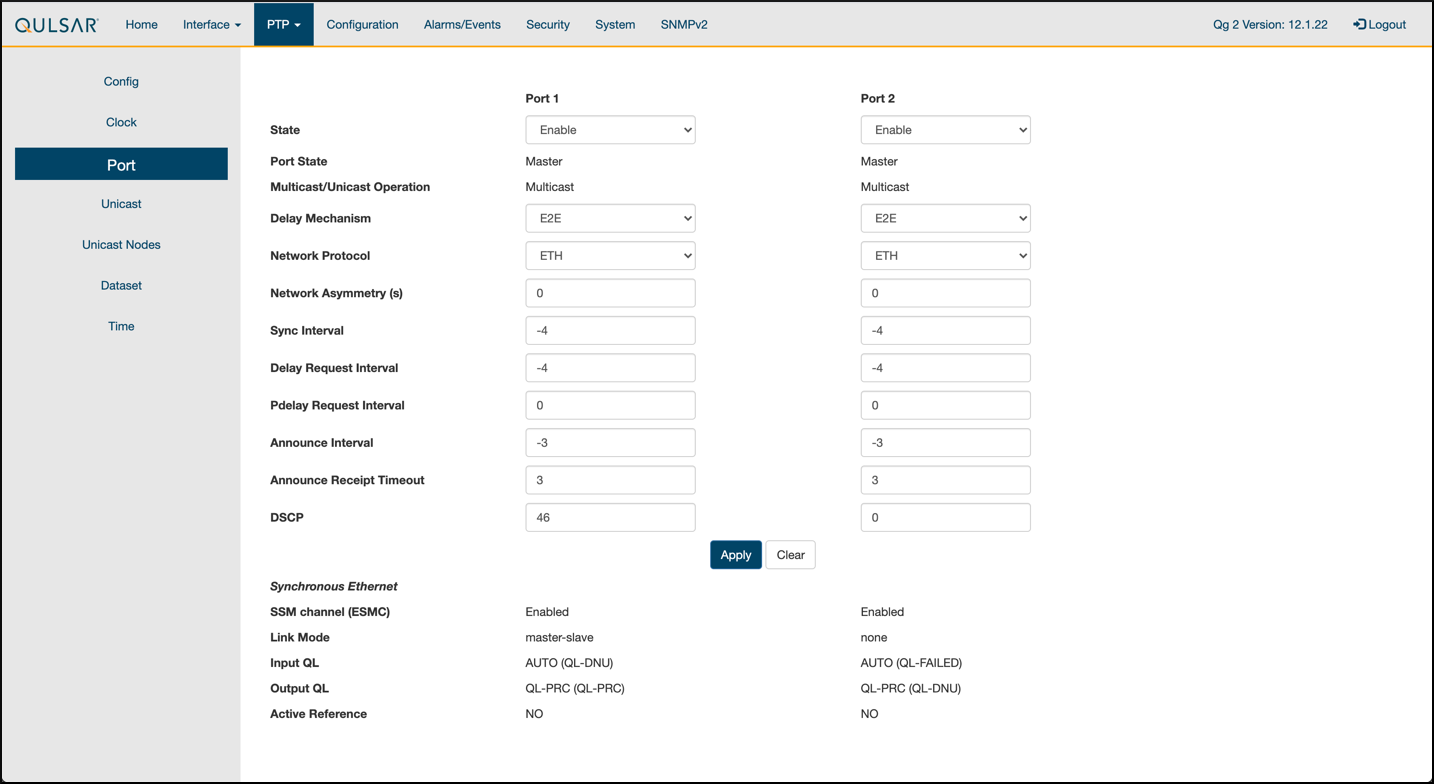
使用 8275.1 配置文件 配置启用主时钟上的端口。
步骤 4。#
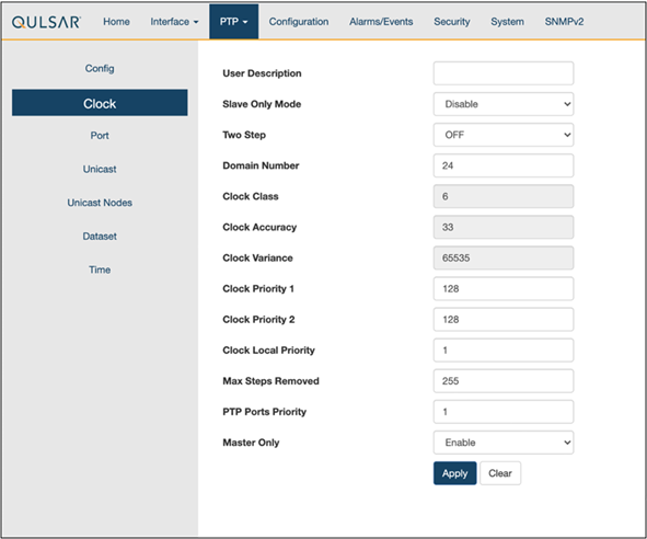
按如下方式配置时钟配置
步骤 5。#
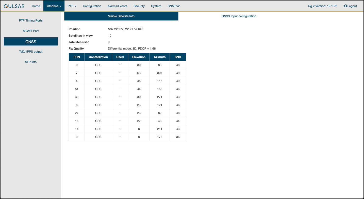
确保 GPS 配置值与 QG2 默认设置保持不变。
步骤 6。#
验证 GPS 信号是否到达主时钟。
第 2.2 章 交换机设置#
第 2.2.1 章 戴尔交换机#
以下示例使用这些 VLAN 2 设置
RU 在端口 1 和 7 上
主时钟在端口 5 上
CN 在端口 11 和 12 上
gNB 端口连接到端口 49 和 51
设置对交换机的 MGMT 访问(在本例中为 172.168.20.67)
OS10# configure terminal
OS10(config)#
interface mgmt1/1/1
no shutdown
no ip address dhcp
ip address 172.16.204.67/22
exit
使用 SSH 访问
admin@172.168.204.67。将端口组 1 和 2 的速度设置为 10G。
OS10(config)#
port-group 1/1/1
mode Eth 10g-4x
exit
port-group 1/1/2
mode Eth 10g-4x
exit
在交换机上启用 PTP。
OS10# configure terminal
OS10(config)#
ptp clock boundary profile g8275.1
ptp domain 24
ptp system-time enable
!
配置主时钟端口。
OS10(config)#
interface ethernet 1/1/5:1
no shutdown
no switchport
ip address 169.254.2.1/24
flowcontrol receive off
ptp delay-req-min-interval -4
ptp enable
ptp sync-interval -4
ptp transport layer2
exit
一段时间后,将打印以下值
<165>1 2023-05-09T07:49:22.625584+00:00 OS10 dn_alm 1021 - - Node.1-Unit.1:PRI [event], Dell EMC (OS10) %PTP_SYSTEM_TIME_NOT_SET: System time is not set. System time will be set when the clock is.
<165>1 2023-05-09T07:51:22.312557+00:00 OS10 dn_alm 1021 - - Node.1-Unit.1:PRI [event], Dell EMC (OS10) %PTP_CLOCK_PHASE_LOCKED: Clock servo is phase locked.
<165>1 2023-05-09T07:51:22.313081+00:00 OS10 dn_alm 1021 - - Node.1-Unit.1:PRI [event], Dell EMC (OS10) %PTP_SYSTEM_TIME_UPDATE_STARTED: System time update service is started. Update interval: 60 minutes.
<165>1 2023-05-09T07:51:59.334346+00:00 OS10 dn_alm 1021 - - Node.1-Unit.1:PRI [event], Dell EMC (OS10) %ALM_CLOCK_UPDATE: Clock changed MESSAGE=apt-daily.timer: Adding 6h 36min 18.719270s random time.
<165>1 2023-05-09T07:57:27.254181+00:00 OS10 dn_alm 1021 - - Node.1-Unit.1:PRI [event], Dell EMC (OS10) %ALM_CLOCK_UPDATE: Clock changed MESSAGE=apt-daily.timer: Adding 4h 31mi
通过创建 VLAN 配置前传网络配置。
注意
如果您选择使用不同的 VLAN,则必须修改 Aerial YAML 文件和 O-RU 配置。C 面和 U 面使用相同的 VLAN。
创建“VLAN 2”。
OS10(config)#
interface vlan 2
OS10(conf-if-vl-2)#
<165>1 2023-03-16T16:51:36.458730+00:00 OS10 dn_alm 813 - - Node.1-Unit.1:PRI [event], Dell EMC (OS10) %IFM_ASTATE_UP: Interface admin state up :vlan2

OS10(conf-if-vl-2)# show configuration
!
interface vlan2
no shutdown
OS10(conf-if-vl-2)# exit
配置 RU、gNB、CN 和 MEC 端口。
配置为低于其最大速度的接口在其名称后附加
:1。这适用于端口组 1 和 2 中的端口。no shutdown switchport mode trunk switchport trunk allowed vlan 2 mtu 8192 flowcontrol receive off ptp enable ptp transport layer2 ptp role timeTransmitter exit
检查 PTP 状态。
OS10# show ptp | no-more
PTP Clock : Boundary
Clock Identity : b0:4f:13:ff:ff:46:63:5f
GrandMaster Clock Identity : fc:af:6a:ff:fe:02:bc:8d
Clock Mode : One-step
Clock Quality
Class : 135
Accuracy : <=100ns
Offset Log Scaled Variance : 65535
Domain : 24
Priority1 : 128
Priority2 : 128
Profile : G8275-1(Local-Priority:-128)
Steps Removed : 1
Mean Path Delay(ns) : 637
Offset From Master(ns) : 1
Number of Ports : 8
----------------------------------------------------------------------------
Interface State Port Identity
----------------------------------------------------------------------------
Ethernet1/1/1:1 Master b0:4f:13:ff:ff:46:63:5f:1
Ethernet1/1/3:1 Master b0:4f:13:ff:ff:46:63:5f:3
Ethernet1/1/5:1 Slave b0:4f:13:ff:ff:46:63:5f:5
Ethernet1/1/7:1 Master b0:4f:13:ff:ff:46:63:5f:8
Ethernet1/1/11 Master b0:4f:13:ff:ff:46:63:5f:4
Ethernet1/1/49 Master b0:4f:13:ff:ff:46:63:5f:9
Ethernet1/1/51 Master b0:4f:13:ff:ff:46:63:5f:10
Ethernet1/1/54 Master b0:4f:13:ff:ff:46:63:5f:2
----------------------------------------------------------------------------
Number of slave ports :1
Number of master ports :7
保存交换机配置
copy running-configuration startup-configuration
第 2.2.2 章 Fibrolan Falcon RX 设置#
尽管 Fibrolan 交换机尚未在 NVIDIA 实验室中获得认证,但 OAI 实验室采用了以下配置和交换机以实现互操作性。
要开始使用,请按照Fibrolan 入门指南进行操作。
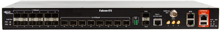
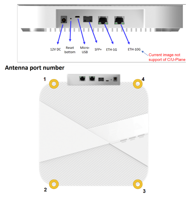
在此设置中,Qulsar 主时钟连接到端口 4,Aerial cuBB 连接到端口 17,富士康 O-RU 连接到端口 16(C/U 面)和端口 15(S/M 面)。您可以忽略下图 [A][B] 中的所有其他端口。
VLAN 设置#
以下假设 VLAN 标签 2 用于 O-RAN CU 平面的控制面和用户面。VLAN 标签 80 用于其他所有内容。
打开 Fibrolan 交换机的配置页面,然后转到 配置 > VLAN。端口 4(Qulsar 主时钟)需要设置为“接入”模式,端口 VLAN 设置为 80。

图 A - VLAN 设置#
对端口 15(RU S/M 面)使用相同的配置。
按如下方式配置端口 16 和 17
模式:“Trunk”
端口:VLAN 80
取消标记端口 VLAN
允许的 VLAN: 2, 80

图 B - VLAN 设置#
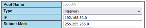
DHCP 设置#
RU M 面需要您设置 DHCP 服务器。转到 配置 > DHCP > 服务器 > 池 并创建一个新的 DHCP 服务器,设置如下
gNB 上的 PTP 设置#
对于 PTP 设置,请按照 Fibrolan PTP 边界时钟配置指南进行操作,并使用以下设置
设备类型:“Ord-Bound”
配置文件:“G8275.1”
时钟域:24
VLAN:80
还要确保启用使用的端口(在本例中为 4、15、16 和 17)。
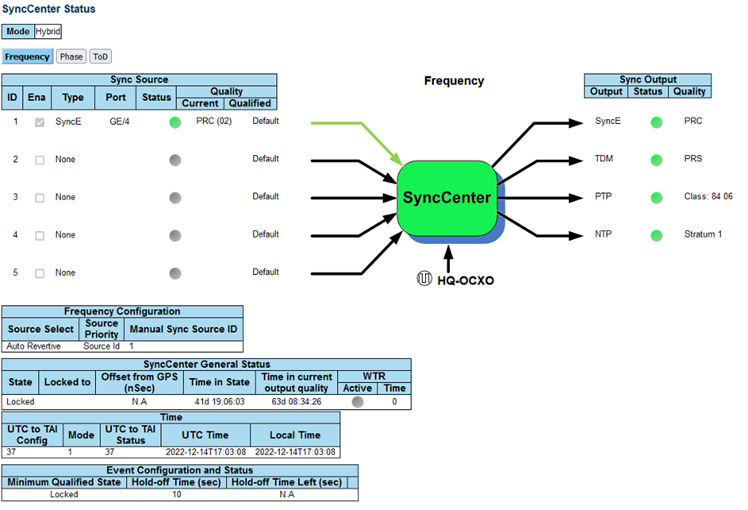
建议使用混合模式作为同步模式。
如果一切配置正确,SyncCenter 应显示绿色。
第 2.3 章 PTP 设置#
这些命令假设 PTP4L 在 ens6f0 NIC 接口上运行,并使用 CPU 核心 9。核心冲突可能会导致问题,因此如果正在使用不同的核心,则 L1 或 L2+ 不得使用该核心。
验证入站 PTP 数据包#
通常,您应该在选定的接口上看到带有 ethertype 0x88f7 的数据包。
sudo tcpdump -i ens6f0 -c 5 | grep ethertype
tcpdump: verbose output suppressed, use -v or -vv for full protocol decode
listening on ens6f1, link-type EN10MB (Ethernet), capture size 262144 bytes
13:27:41.291503 48:b0:2d:63:83:ac (oui Unknown) > 01:1b:19:00:00:00 (oui Unknown), ethertype Unknown (0x88f7), length 60:
13:27:41.291503 48:b0:2d:63:83:ac (oui Unknown) > 01:1b:19:00:00:00 (oui Unknown), ethertype Unknown (0x88f7), length 60:
13:27:41.296727 c4:5a:b1:14:1a:c6 (oui Unknown) > 01:1b:19:00:00:00 (oui Unknown), ethertype Unknown (0x88f7), length 78:
13:27:41.296784 c4:5a:b1:14:1a:c6 (oui Unknown) > 01:1b:19:00:00:00 (oui Unknown), ethertype Unknown (0x88f7), length 60:
13:27:41.306316 08:c0:eb:71:e7:d5 (oui Unknown) > 01:1b:19:00:00:00 (oui Unknown), ethertype Unknown (0x88f7), length 58:
创建 ptp4l 配置文件#
将这些命令粘贴到 shell 中以创建三个配置文件
cat <<EOF | sudo tee /etc/ptp.conf
[global]
priority1 128
priority2 128
domainNumber 24
tx_timestamp_timeout 30
dscp_event 46
dscp_general 46
logging_level 6
verbose 1
use_syslog 0
logMinDelayReqInterval 1
[ens6f0]
logAnnounceInterval -3
announceReceiptTimeout 3
logSyncInterval -4
logMinDelayReqInterval -4
delay_mechanism E2E
network_transport L2
EOF

cat <<EOF | sudo tee /lib/systemd/system/ptp4l.service
[Unit]
Description=Precision Time Protocol (PTP) service
Documentation=man:ptp4l

[Service]
Restart=always
RestartSec=5s
Type=simple
ExecStart=/usr/bin/taskset -c 9 /usr/sbin/ptp4l -f /etc/ptp.conf

[Install]
WantedBy=multi-user.target
EOF
创建 phc2sys 配置文件#
# If more than one instance is already running, kill the existing
# PHC2SYS sessions.

# Command used can be found in /lib/systemd/system/phc2sys.service
# Update the ExecStart line to the following, assuming ens6f0 interface is used.
  sudo nano /lib/systemd/system/phc2sys.service

[Unit]
Description=Synchronize system clock or PTP hardware clock (PHC)
Documentation=man:phc2sys
After=ntpdate.service
Requires=ptp4l.service
After=ptp4l.service

[Service]
Restart=always
RestartSec=5s
Type=simple
ExecStart=/bin/sh -c "taskset -c 9 /usr/sbin/phc2sys -s /dev/ptp$(ethtool -T ens6f0 | grep PTP | awk '{print $4}') -c CLOCK_REALTIME -n 24 -O 0 -R 256 -u 256"

[Install]
WantedBy=multi-user.target
启用并启动 phc2sys 和 ptp4l#
更改配置文件后,需要重新加载、启用和重启它们。如果这些服务不同步,则可以重启它们。
sudo systemctl daemon-reload
sudo systemctl enable ptp4l.service
sudo systemctl enable phc2sys.service

sudo systemctl restart phc2sys.service ptp4l.service

# check that the service is active and has low rms value (<30):
systemctl status ptp4l.service phc2sys.service
● ptp4l.service - Precision Time Protocol (PTP) service
     Loaded: loaded (/lib/systemd/system/ptp4l.service; enabled; vendor preset: enabled)
     Active: active (running) since Tue 2023-05-09 13:21:12 UTC; 14s ago
       Docs: man:ptp4l
   Main PID: 6962 (ptp4l)
      Tasks: 1 (limit: 94588)
     Memory: 544.0K
     CGroup: /system.slice/ptp4l.service
             └─6962 /usr/sbin/ptp4l -f /etc/ptp.conf

May 09 13:21:17 aerial-rf-gb-gnb taskset[6962]: ptp4l[15552.609]: rms   15 max   32 freq   -639 +/-  25 delay   211 +/-   1
May 09 13:21:18 aerial-rf-gb-gnb taskset[6962]: ptp4l[15553.609]: rms   21 max   29 freq   -583 +/-  12 delay   210 +/-   1
May 09 13:21:19 aerial-rf-gb-gnb taskset[6962]: ptp4l[15554.609]: rms   11 max   21 freq   -576 +/-   8 delay   211 +/-   1
May 09 13:21:20 aerial-rf-gb-gnb taskset[6962]: ptp4l[15555.609]: rms    6 max   13 freq   -579 +/-   8 delay   211 +/-   1
May 09 13:21:21 aerial-rf-gb-gnb taskset[6962]: ptp4l[15556.609]: rms    4 max    7 freq   -578 +/-   6 delay   212 +/-   0
May 09 13:21:22 aerial-rf-gb-gnb taskset[6962]: ptp4l[15557.609]: rms    5 max   11 freq   -589 +/-   6 delay   213 +/-   1
May 09 13:21:23 aerial-rf-gb-gnb taskset[6962]: ptp4l[15558.609]: rms    6 max   12 freq   -593 +/-   8 delay   210 +/-   1
May 09 13:21:24 aerial-rf-gb-gnb taskset[6962]: ptp4l[15559.609]: rms    3 max    7 freq   -587 +/-   5 delay   211 +/-   1
May 09 13:21:25 aerial-rf-gb-gnb taskset[6962]: ptp4l[15560.609]: rms    5 max   12 freq   -582 +/-   7 delay   212 +/-   1
May 09 13:21:26 aerial-rf-gb-gnb taskset[6962]: ptp4l[15561.609]: rms    4 max    7 freq   -587 +/-   7 delay   213 +/-   1

● phc2sys.service - Synchronize system clock or PTP hardware clock (PHC)
     Loaded: loaded (/lib/systemd/system/phc2sys.service; enabled; vendor preset: enabled)
     Active: active (running) since Tue 2023-05-09 13:21:12 UTC; 14s ago
       Docs: man:phc2sys
   Main PID: 6963 (phc2sys)
      Tasks: 1 (limit: 94588)
     Memory: 572.0K
     CGroup: /system.slice/phc2sys.service
             └─6963 /usr/sbin/phc2sys -a -r -n 24 -R 256 -u 256

May 09 13:21:17 aerial-rf-gb-gnb phc2sys[6963]: [15553.320] CLOCK_REALTIME rms   42 max   79 freq  +8240 +/- 368 delay  1762 +/-  16
May 09 13:21:18 aerial-rf-gb-gnb phc2sys[6963]: [15554.336] CLOCK_REALTIME rms   35 max   64 freq  +8091 +/- 303 delay  1754 +/-  13
May 09 13:21:19 aerial-rf-gb-gnb phc2sys[6963]: [15555.352] CLOCK_REALTIME rms   27 max   52 freq  +8218 +/- 224 delay  1752 +/-  13
May 09 13:21:20 aerial-rf-gb-gnb phc2sys[6963]: [15556.368] CLOCK_REALTIME rms   21 max   49 freq  +8153 +/- 152 delay  1758 +/-  16
May 09 13:21:21 aerial-rf-gb-gnb phc2sys[6963]: [15557.384] CLOCK_REALTIME rms   17 max   39 freq  +8149 +/- 125 delay  1761 +/-  16
May 09 13:21:22 aerial-rf-gb-gnb phc2sys[6963]: [15558.400] CLOCK_REALTIME rms   14 max   33 freq  +8185 +/- 101 delay  1750 +/-  14
May 09 13:21:23 aerial-rf-gb-gnb phc2sys[6963]: [15559.416] CLOCK_REALTIME rms   12 max   32 freq  +8138 +/-  63 delay  1752 +/-  13
May 09 13:21:24 aerial-rf-gb-gnb phc2sys[6963]: [15560.431] CLOCK_REALTIME rms   11 max   43 freq  +8171 +/-  54 delay  1756 +/-  15
May 09 13:21:25 aerial-rf-gb-gnb phc2sys[6963]: [15561.447] CLOCK_REALTIME rms   10 max   32 freq  +8163 +/-  38 delay  1762 +/-  16
May 09 13:21:26 aerial-rf-gb-gnb phc2sys[6963]: [15562.463] CLOCK_REALTIME rms    9 max   23 freq  +8162 +/-  17 delay  1761 +/-  16
禁用 NTP#
使用以下命令关闭 NTP
sudo timedatectl set-ntp false
timedatectl
Local time: Thu 2022-02-03 22:30:58 UTC
           Universal time: Thu 2022-02-03 22:30:58 UTC
                 RTC time: Thu 2022-02-03 22:30:58
                Time zone: Etc/UTC (UTC, +0000)
System clock synchronized: no
              NTP service: inactive
          RTC in local TZ: no
验证系统时钟同步#
使 NTP 处于非活动状态并同步系统时钟
timedatectl
Local time: Thu 2022-02-03 22:30:58 UTC
           Universal time: Thu 2022-02-03 22:30:58 UTC
                 RTC time: Thu 2022-02-03 22:30:58
                Time zone: Etc/UTC (UTC, +0000)
System clock synchronized: yes
              NTP service: inactive
          RTC in local TZ: no
第 2.4 章 设置富士康 ORU#
提示
有一个关于设置富士康 ORU 的 教程视频。
富士康 RPQN-7801E |
连接和设置 |
|---|---|
|
连接
主时钟设置(Qulsar)
|
在 gNB 服务器上配置 VLAN 和 IP 地址#
将这些命令添加到服务器启动脚本 (
/etc/rc.local) 中,以便它们在重启时自动运行。在前传端口上配置这些设置。
您必须使用与以下示例中不匹配的 IP 地址
sudo ip link add link ens6f0 name ens6f0.2 type vlan id 2
sudo ip addr add 169.254.1.103/24 dev ens6f0.2
sudo ip link set up ens6f0.2
O-RU M 面设置#
将以下内容添加到
/etc/profile的底部,如果set_qse.sh行已存在,请将其注释掉。最初将接口设置为eth0用于固件版本 1,升级到固件版本 2 或更高版本后设置为qse-eth。interface=eth0 vlanid=2 ipLastOctet=20 ip link add link ${interface} name ${interface}.$vlanid type vlan id $vlanid ip addr flush dev ${interface} ip addr add 169.254.0.0/24 dev ${interface} ip addr add 169.254.1.${ipLastOctet}/24 dev ${interface}.$vlanid ip link set up ${interface}.$vlanid
使用命令
./reboot.sh重启 O-RU 并检查网络配置# ip r 169.254.1.0/24 dev eth0.2 src 169.254.1.20
更新 O-RU 配置#
注意
如果您正在使用 CBRS O-RU(富士康 RPQN-4800E),请参考以下注释了解修改后的配置。
更新
/home/root/test/RRHconfig_xran.xml中的 O-RU 配置。root@arria10:~/test# grep -v '<!-' RRHconfig_xran.xml RRH_DST_MAC_ADDR = 08:c0:eb:71:e7:d4 # To match fronthaul interface of DU RRH_SRC_MAC_ADDR = 6C:AD:AD:00:04:6C # To match qse-eth of RU RRH_EN_EAXC_ID = 0 RRH_EAXC_ID_TYPE1 = 0x0, 0x1, 0x2, 0x3 RRH_EAXC_ID_TYPE3 = 0x8, 0x9, 0xA, 0xB RRH_EN_SPC = 1 RRH_RRH_LTE_OR_NR = 1 RRH_TRX_EN_BIT_MASK = 0x0f RRH_RF_EN_BIT_MASK = 0x0f RRH_CMPR_HDR_PRESENT = 0 RRH_CMPR_TYPE = 1, 1 RRH_CMPR_BIT_LENGTH = 9, 9 RRH_UL_INIT_SYM_ID = 0 RRH_TX_TRUNC_BITS = 4 RRH_RX_TRUNC_BITS = 4 RRH_MAX_PRB = 273 RRH_C_PLANE_VLAN_TAG = 0x0002 #To match vlan id set in cuphycontroller yaml file RRH_U_PLANE_VLAN_TAG = 0x0002 #To match vlan id set in cuphycontroller yaml file RRH_SLOT_TICKS_IN_SEC = 2000 RRH_SLOT_PERIOD_IN_SAMPLE = 61440 RRH_LO_FREQUENCY_KHZ = 3750000, 0 RRH_TX_POWER = 24, 24 RRH_TX_ATTENUATION = 12.0, 12.0, 12.0, 12.0 RRH_RX_ATTENUATION = 0.0, 0.0, 0.0, 0.0 RRH_BB_GENERAL_CTRL = 0x0, 0x0, 0x0, 0x0 RRH_RF_GENERAL_CTRL = 0x3, 0x1, 0x0, 0x0 RRH_PTPV2_GRAND_MASTER_MODE = 3 RRH_PTPV2_JITTER_LEVEL = 0 RRH_PTPV2_VLAN_ID = 0 RRH_PTPV2_IP_MODE = 4 RRH_PTPV2_GRAND_MASTER_IP = 192.167.27.150 RRH_PTPV2_SUB_DOMAIN_NUM = 24 RRH_PTPV2_ACCEPTED_CLOCK_CLASS = 135 RRH_TRACE_PERIOD = 10 RRH_DL_IQ_SCALING = 0x1001 RRH_CFR_PEAK_THRESHOLD = 0.5
注意
在富士康固件版本 2.6.9 中,配置文件位于
/home/root/sdcard中。注意
以上配置来自运行固件 3.1.15 的 ORU。
注意
如果您使用 CBRS O-RU(富士康 RPQN-4800E),则应按如下方式修改上述参数
n78
RRH_LO_FREQUENCY_KHZ = 3750000, 0n48 (CBRS)
RRH_LO_FREQUENCY_KHZ = 3649140, 0
重启 O-RU。
cd /home/root/test/

./reboot
运行以下命令以启用配置
cd /home/root/test/

./init_rrh_config_enable_cuplane
要查看 ORU 状态,请运行以下脚本。
cd /home/root/test/

./chk_con.sh